Getting a hefty 12kW solar inverter system working with three 16kWh LiFePO4 battery banks means I needed serious copper and no compromises on the work. With 48kWh of total energy storage, there are hundreds of amps of potential fault current sitting behind every connection point. If I let the cable routing get messy or used mismatched busbars, I knew terminal heat spikes would start fast. Doing this job correctly demands industrial-grade wire management, high-amperage circuit breakers, and a systematic approach to pre-charge testing.
Verifying 24-Hour Off-Grid Performance Under Heavy Load (23:13)⚡ Quick Guide: How to Make It in 15 Steps
- Route battery lines through organized trunking.
- Crimp thick 1/0 AWG welding cable.
- Power single pack and test trip.
- Engage all packs to balance DC.
- Terminate solar wires using tight ferrules.
- Hook solar strings into DC breakers.
- Verify line input and load output.
- Mount automated rail fire suppression canister.
- Land grid utility lines and ground.
- Bond system neutral and equipment grounds.
- Connect transfer switch to main panel.
- Clear inverter capacitors before breaker reset.
- Daisy-chain battery BMS communication network cables.
- Power inverter and confirm battery telemetry.
- Monitor overnight residential loads without sunlight.
📋 In This Article
- Technical Specifications & Components
- Tools & Materials Used — what you will need for this project
- Mounting Busbars and Routing Main Battery Cables
- Crimping 1/0 AWG Welding Cable Leads
- Initial Single-Pack Inverter Inrush Current Test
- Parallel Battery Engagement and Pre-Charge Balancing
- Installing Wire Ferrules and DC Surge Arresters
- Wiring PV1 and PV2 High-Voltage Solar Inputs
- Terminating MPPT Terminals and Verifying String Polarity
- Mounting Thermal-Activated Din-Rail Fire Extinguishers
- Wiring Grid Input Lines to the AC Service Breaker
- Bonding Neutral Buses and Inverter AC Output Lines
- Connecting the Automatic Transfer Switch and Phasing
- Discharging Residual Inverter Bus Voltage
- Daisy-Chaining Parallel Battery BMS Communication
- Powering Up the 12kW Inverter and Reading Live Telemetry
- Verifying 24-Hour Off-Grid Performance Under Heavy Load
- FAQ
📊 Technical Specifications & Components
| Inverter Rated Output | 12 kW |
| Individual Battery Bank Capacity | 16 kWh |
| Total Energy Storage Bank | 48 kWh (3 x 16 kWh parallel packs) |
| Main DC Busbar Rating | 650 Amps |
| Primary Battery Interconnect Cable | 1/0 AWG Heavy-Duty Flexible Welding Wire |
| AC Transfer Switch Spec | 100A, 220V Double Throw |
| Grid Breaker Sizing | 50A AC Miniature Circuit Breaker (120V/240V) |
| BMS Communication Topology | Daisy-Chain RJ45 (PCS Master to Inverter CAN/RS485) |
| Solar String Protection | 2-in 2-out DC Breakers with Integrated Class II SPDs |
| Fire Suppression | Thermal-Actuating Rail Fire Extinguisher Unit |
📊 Project Overview & Costs
🔧 Difficulty Level: Hard
⏱️ Time Investment: DIY: 14 - 18 Hours | Pro: 6 - 8 Hours
💰 Professional Service Cost: $2,200 - $3,500
💡 Verdict: Self-performing panel layout, trunking, and high-amperage busbar terminations retains thousands of dollars of electrical contractor labor in personal savings.
🛠️ Tools & Materials Used
• Heavy-duty hydraulic cable crimper
• Slotted wire trunking raceways
• 650A DC copper busbar block
• High-capacity DC battery breaker switch
• 100A 220V dual-power automatic transfer switch
• 50A 120V/240V miniature AC circuit breaker
• Rail-mounted automated fire extinguisher tube
• Insulated terminal ferrules set
• Step drill bit and power drill
Step-by-Step Guide
Mounting Busbars and Routing Main Battery Cables
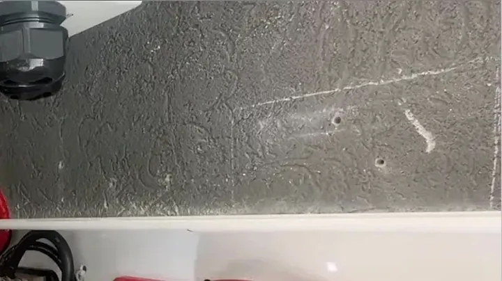
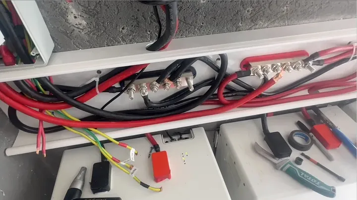
The first thing I did was drill clear pass-through holes into the cabinet raceways. This gives the hefty battery leads a straight, clean run. I mounted the slotted wire trunking directly to the wall to keep this high-voltage DC setup as tidy as possible. I routed every single battery cable neatly through the side tracks, aiming toward the heavy copper busbar. No random coils dangling inside the box; I cut them clean.
I trimmed all the conductors to uniform lengths, making sure there was zero excess bulk bunching up around the copper terminals. Plastic zip ties cinch the cables flush against the backboard, which really helps kill mechanical strain on the lugs. The 650A busbar sits centered, right where the positive and negative groups divide cleanly. I positioned the high-amperage battery breaker deliberately on the side rail, so routing straight up and over into the inverter lugs requires minimal bend radius. Smooth operation is key.
Crimping 1/0 AWG Welding Cable Leads
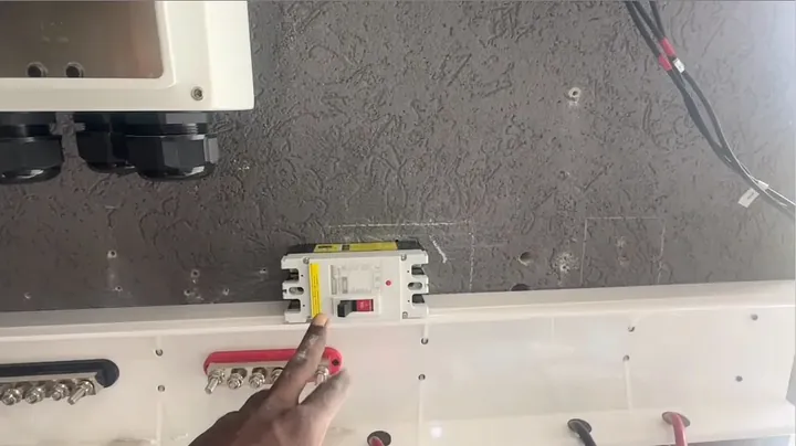
I always go with thick wire because it handles high continuous amps without turning into a room heater. For this job, I grabbed 1/0 AWG (one-aught) welding wire instead of standard stiff battery cable. This flexible, fine-strand welding copper bends tight around sharp cabinet corners without snapping any inner cores. It feels solid in your hand. I stripped the heavy neoprene insulation carefully, making sure not to nick the copper strands underneath.
Then, I slid heavy-duty tin-plated copper lugs over the bare strands, ensuring I got full insertion depth. I positioned each lug firmly inside the crimping dies before pumping the hydraulic ram down. After every finished crimp, I gave it an aggressive tug test. If it moved even a fraction of a millimeter, I cut it off and redid it. I ran these heavy lines between the breaker load terminals and the busbar plates, making sure everything was secure.
Initial Single-Pack Inverter Inrush Current Test
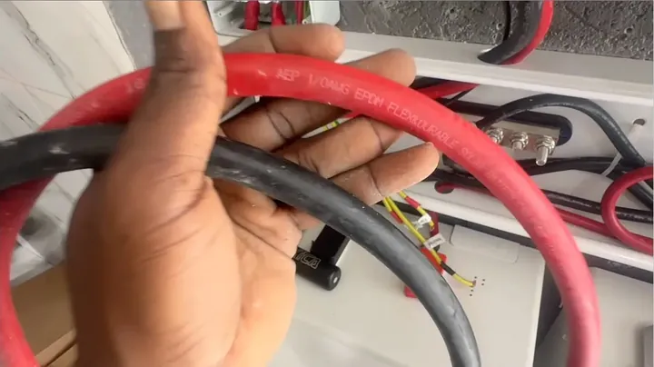
It was time to test the DC link before I bolted everything permanently shut. I powered up just one 16kWh lithium battery pack using its front soft-switch. Then, I flipped the massive DC battery breaker upward into the active circuit position. It tripped immediately. The internal battery management system threw a fault light instantly. Inverter filter capacitors draw huge inrush current the split second a breaker closes across a dead-cold bus.
That massive inductive snap sounds like a miniature hammer strike inside the chassis. I switched the inverter master switch to the discharge position to completely drain any residual tank energy. Then, I reset the breaker. I tried firing it up a second time. Fault tripped again. Not ideal.
Parallel Battery Engagement and Pre-Charge Balancing
Look, fighting capacitive inrush with a single battery pack BMS limit is a losing battle. The internal BMS overcurrent safety shuts down instantly to protect its switching FETs. I turned on all three 16kWh batteries simultaneously so their combined discharge paths would divide the initial capacitor surge current across all three banks. Solid green lights. No fault codes anywhere across the front display panels.
I threw the main battery breaker. The breaker clicked into place securely without tripping. Then, I engaged the 12kW inverter's main switch. The unit woke up immediately with active cooling fans whirring smoothly to life.
Once the DC bus was pre-charged, I closed the breaker cover and secured the hardware. That worked.
Installing Wire Ferrules and DC Surge Arresters
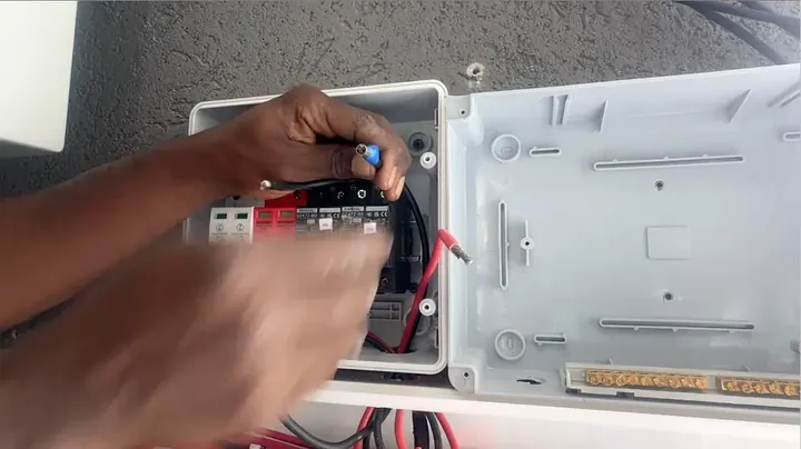
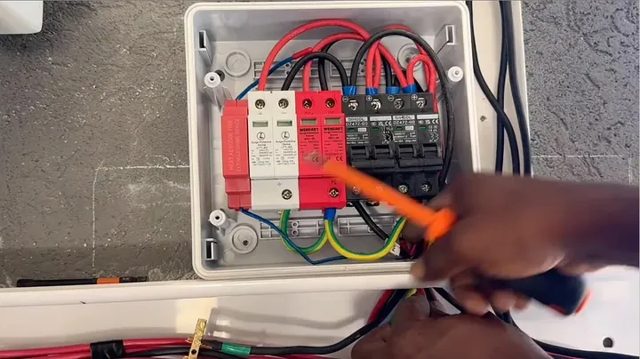
Bare stranded wires mashed under screw cage terminals are a fire hazard waiting to happen, so I crimped insulated copper ferrules onto every single DC solar lead before slipping them into the terminals. Ferrules distribute screw tension evenly without severing delicate, hair-thin copper wire strands. I ran positive solar inputs directly into the top side of the DC surge protection devices (SPD) and matching circuit breakers.
I paralleled the grounding terminal tabs directly across both arresters using bare copper bonding links. Then, I routed the heavy bare ground conductor straight from the SPD block down to the subpanel earth grounding bar. A dedicated copper grounding rod outside takes the direct lightning discharge hit if an overhead surge punches through the array. I tied the utility neutral and grounding buses together precisely according to local code bonding specs, making sure everything was up to snuff.
Wiring PV1 and PV2 High-Voltage Solar Inputs
I always keep solar strings separated and marked before shoving leads into the raceways. PV1 and PV2 enter through side conduit knockouts, coming straight from the outdoor solar array. I stripped back the dual-wall XLPO insulation and slid terminal ferrules over each lead. Positive lands on the left breaker pole, and negative lands right next to it.
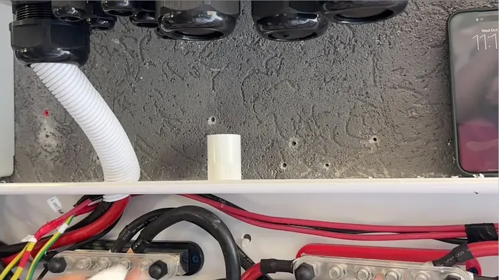
I double-checked each string carefully; connecting reversed polarity to an MPPT tracker blows the input stage diodes instantly, and I didn't want that. I routed the outgoing feeder lines from the bottom of each DC breaker straight over into the inverter's dedicated solar input bay. Drilling pass-through holes directly beneath the solar terminal block saves excessive conduit bends. Neat wiring saves hours of diagnostic headaches down the road. Every time.
Terminating MPPT Terminals and Verifying String Polarity
The line side always goes to the top; the load side feeds directly out of the bottom to the inverter. I stripped the lower conductor ends, slipped on the ferrules, and firmly torqued down each breaker clamp screw. The 12kW inverter features heavy-duty mechanical clamp terminals for each separate MPPT channel. I paid close attention to the terminal stamping because negative and positive are intentionally staggered across the board layout. Snugging a negative lead into a positive lug causes massive short circuits.
I grabbed a calibrated digital multimeter set to DC volts. I probed across PV1 positive and negative terminals, then confirmed the exact same open-circuit voltage reading across the PV2 lugs. The meter confirmed positive potential cleanly, with zero negative sign on the display. That's what I wanted to see.
Mounting Thermal-Activated Din-Rail Fire Extinguishers
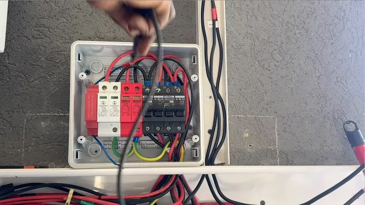
High-voltage solar DC boxes can pack some serious heat under continuous loads. I clipped a self-actuating rail fire extinguisher directly onto the top DIN rail, right above the breaker array. If an electrical arc fires up or a loose terminal generates runaway resistive heat, direct flame ruptures the thermal sensor on the canister. It then dumps a clean extinguishing agent instantly throughout the entire enclosed cabinet space.
No messy powders, just rapid fire suppression right at the ignition source. After that, I moved over to the AC distribution panel once the safety extinguisher was clipped tight. I drilled standard conduit knockouts along the bottom sheet metal for grid line access. Then I prepared the 50A dual-pole AC breaker and surge suppressor combo block for installation.
Wiring Grid Input Lines to the AC Service Breaker
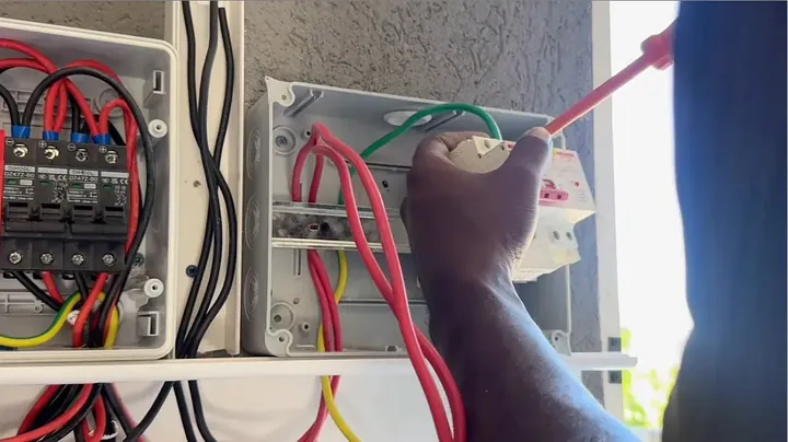
The incoming utility power from the grid feeds directly through the main feeder conduit into the subpanel. I stripped back the heavy gauge utility line conductors cleanly. I terminated incoming line 1 (L1) and line 2 (L2) directly into the top line terminals of the 50A breaker. I torqued them down tight. A loose lug under 50 amps of continuous house load scorches terminal plastic in months, so I'm always careful there.
I routed the heavy green grounding conductor directly into the subpanel's primary ground bus bar. I made sure to keep one spare lug terminal empty on the ground bus for any future bonding runs. Finally, I fed outgoing load wires from the breaker's bottom lugs straight across to line 2 on the dual-power automatic transfer switch.
Bonding Neutral Buses and Inverter AC Output Lines
I set up a dedicated isolated neutral bar alongside the equipment grounding bus. I ran a heavy insulated neutral jumper conductor from the inverter AC output straight onto the neutral bar. I tied this system neutral firmly back to the ground bar directly at the main bonding point to prevent floating voltages across split-phase loads. I pulled two heavy lines for the inverter AC load output (L1 and L2).
I routed them neatly underneath the raceway trunking and brought them up into the line side of the secondary AC sub-breaker. This dedicated breaker safeguards the inverter's sensitive internal power electronics from external load short circuits. Everything stays clean, separated, and marked, just how I like it.
Connecting the Automatic Transfer Switch and Phasing
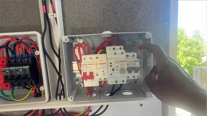
The automatic transfer switch dictates where the house pulls power during outages, plain and simple. Solar inverter power feeds line input 1 as the primary default energy source. Grid utility power sits on line input 2 as the emergency backup feed. I replaced any temporary black phasing tape with bright red electrical tape on line 2 conductors to keep split-phase lines easily identifiable at a glance.
I fed load outputs from the bottom transfer switch lugs directly out to the home's primary breaker panel. Then, I flipped the UPS transfer switch to automatic mode. The indicator LED snapped on bright green for line 2. Utility power hums steadily through the box while solar arrays remain offline for final checks. That's how it's done.
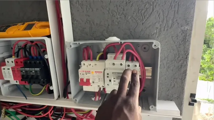
Discharging Residual Inverter Bus Voltage
Before doing the final start-up runs, I needed to verify that the battery bank started cleanly without any residual bus cross-talk. I threw the battery breaker up. An unexpected red fault LED blinked aggressively on the battery interface. I shut it down. Turning the breaker on while the inverter circuitry holds partial unreferenced DC charge tricks the internal battery BMS into an abnormal voltage detection fault. I turned the inverter switch off.
Then, I flipped the battery breaker open again. I discharged every millivolt of residual trapped current out of the inverter's large electrolytic capacitors. Cycling the system power switch with main DC isolated burns off trapped rail charge. It's a critical step.
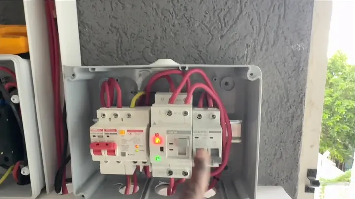
Daisy-Chaining Parallel Battery BMS Communication
Three 16kWh lithium batteries cannot operate as a unified bank without tight telemetry communication, so I handled that next. I plugged an RJ45 patch cable from the master battery pack's PCS port directly into the inverter's CAN/RS485 communications jack. I then daisy-chained the remaining two packs using standard RJ45 communication jumpers from the master battery's OUT port to the second pack's IN port.
I repeated this link from pack two's OUT port to pack three's IN port. That completed the loop. I cycled all three battery power buttons simultaneously with the inverter drained. Zero fault codes. I then closed the breaker box and switched the main DC disconnect up. Perfect.
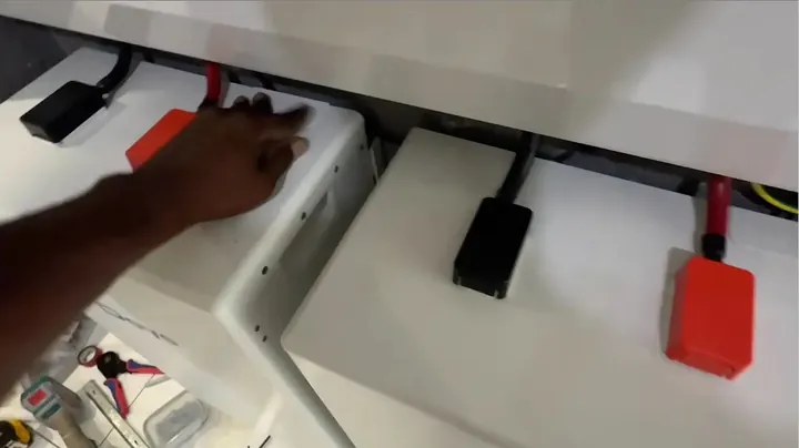
Powering Up the 12kW Inverter and Reading Live Telemetry
I switched the inverter power toggle on. Internal contactors engaged with a crisp mechanical snap. The full-color LCD interface lit up, booted its operating firmware, and synced directly with the master battery BMS over CAN bus. At first, the state of charge showed 100% default calibration before live packet polling completed. I gave it ten seconds.
The display updated cleanly to show an exact 75% state of charge across the entire 48kWh bank. I then turned on the solar DC breakers. High-voltage arrays take roughly thirty to forty seconds to calibrate sweep cycles before the MPPT engages bulk charging. The automatic transfer switch shifted smoothly over to solar priority. That's a good sight.
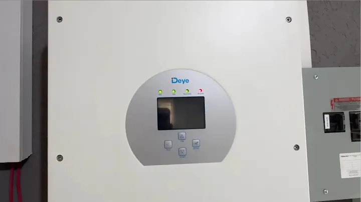
Verifying 24-Hour Off-Grid Performance Under Heavy Load
True reliability is proven when the sky stays dead gray all day long. A massive overcast storm system dumped rain over the property for twenty-four consecutive hours, starving the arrays of harvestable sun. Starting from a modest 71% battery state of charge, the three 16kWh packs powered the entire residential property without breaking a sweat. After a full twenty-four hours of run-time, the bank still read 56% capacity remaining. That's true energy independence. A complete turn-key 12kW inverter setup with 48kWh of LiFePO4 storage represents a serious investment, but it eliminates grid outages entirely. No more worries.
⚠️ CAUTION: SAFETY WARNING!
Working with a 48kWh lithium battery bank and 650A busbars presents severe electrical arc flash and high-current short circuit risks. Always use fully insulated tools, double-check polarity with a calibrated multimeter before closing disconnects, and never service energized high-voltage DC terminals.
Summary & Tips
Building a multi-battery 12kW solar setup demands patience, heavy copper conductors, and zero shortcuts. Crimping proper ferrules and installing DIN-rail fire suppression protects my property against catastrophic electrical failures. Cycling and pre-charging inverter capacitors solves nuisance BMS tripping before it turns into a nightmare. Do the job right the first time and your home will sail smoothly through any grid blackout. It's worth the effort.
📋 FAQ
❓ Why did the battery breaker trip when turning on just one battery pack?
Inverters contain large internal electrolytic filter capacitors on the DC input bus. When a breaker engages a cold inverter, those empty capacitors draw an instantaneous rush of current. This current surge mimics a dead short circuit to the battery's Battery Management System (BMS). A single 16kWh pack's overcurrent protection threshold trips instantly to safeguard internal electronics. Activating all three packs in parallel distributes that split-second current spike among three separate protection circuits, allowing capacitors to charge without tripping.
❓ Why use flexible welding cable instead of standard battery cables?
Standard battery cable consists of coarse copper strands that resist bending inside confined electrical enclosures. Fine-strand 1/0 AWG welding cable bends easily around tight corners without imposing physical strain on terminal lugs or busbar bolts. It sustains high continuous currents without developing loose connections over time. Essential is the use of proper heavy-duty crimp lugs designed for fine-strand copper.
❓ What is the purpose of the thermal rail fire extinguisher inside the DC box?
High-voltage DC solar strings generate extreme continuous heat if a terminal lug loosens or a circuit breaker fails internally. Direct current arcs do not easily extinguish spontaneously, unlike alternating current. If an arc ignites the plastic enclosure, the thermal-actuating fire extinguisher burst sensor activates and blankets the enclosed space with clean extinguishing gas before flames spread to surrounding building structures.
❓ How do parallel LiFePO4 batteries communicate with the hybrid inverter?
Communication occurs via an RJ45 patch cable network utilizing CAN or RS485 protocols. The primary battery pack connects its main PCS communication port directly to the inverter's dedicated BMS jack to transmit overall bank telemetry. Secondary and tertiary packs link to the master using an OUT-to-IN daisy-chain loop, enabling the inverter to accurately read total combined capacity, temperature, and charging limits.
❓ Why are wire ferrules necessary on solar wire connections?
Bare multistrand solar wire separates and spreads when compressed directly under terminal screws. Over time, vibration and thermal expansion cause loose strands to oxidize, creating high-resistance hot spots that melt terminal blocks. Crimp-on insulated wire ferrules compact every individual wire strand into a single solid copper pin. This solid mechanical cylinder provides the terminal clamp with maximum surface contact and eliminates stray wires.
Disclaimer: I purchased all tools for this guide with my own money to ensure an unbiased review. This post contains affiliate links, meaning I earn a small commission if you make a purchase at no extra cost to you.