0.2 mm layer height is the standard I use for my test prints, yet that’s exactly where I see those frustrating hull lines appearing on my box lids. I’ve spent hours testing different slicer configurations to understand why these artifacts form. By analyzing layer times and material cooling, I’ve identified the root causes and developed reliable fixes for these common 3D printing defects.
⚡ Quick Guide: How to Make It in 15 Steps
- Print a test lid at 0.2 mm layer height to isolate the hull line defect.
- Analyze layer times in the slicer to correlate long print durations with visible artifacts.
- Adjust minimum layer time to 150 seconds to test for uniform shrinkage.
- Decouple walls from solid layers by increasing upper wall thickness in CAD.
- Set top and infill overlap to 0% or negative values to create a stress-relieving gap.
- Enable precise wall settings to reduce overlap and improve outer wall consistency.
- Add chamfers to all floor edges to separate high-mass solid layers from outer walls.
- Apply fuzzy skin or patterns to hide remaining surface artifacts.
📋 In This Article
- Technical Specifications & Components
- Tools & Materials Used — what you will need for this project
- Setting Up the Test Print
- Analyzing Layer Time Discrepancies
- Testing Layer Time Uniformity
- Identifying Shrinkage as the Root Cause
- Implementing Decoupling Techniques
- Comparing Decoupling Solutions
- Optimizing Wall Printing Order
- Using CAD for Design Decoupling
- Controlling Shrinkage with Cooling
- Achieving Uniform Print Speeds
- Refining Functional Edges
- Adjusting Vertical Shell Thickness
- Hiding Artifacts with Fuzzy Skin
- Using Chamfers and Fillets to Confuse
- Finalizing Design for Clean Prints
- FAQ
📊 Technical Specifications & Components
| Layer Height | 0.2 mm |
| Minimum Layer Time | 150 seconds |
| Top/Infill Overlap | 0% to 15% |
| Cooling Fan Speed | 100% for PLA |
| Wall Printing Order | Inner-Outer-Inner |
📊 Project Overview & Costs
🔧 Difficulty Level: Medium
⏱️ Time Investment: DIY: 2-4 hours of test printing | Pro: 1 hour of slicer optimization
💰 Professional Service Cost: $0 (software-based fix)
💡 Verdict: I saved my entire batch of prints by adjusting slicer settings rather than scrapping the models.
🛠️ Tools & Materials Used
• Orca Slicer
• Alibre CAD Software
• Calibrated PLA Filament
Fixing 3D Print Hull Lines: Step-by-Step
Setting Up the Test Print
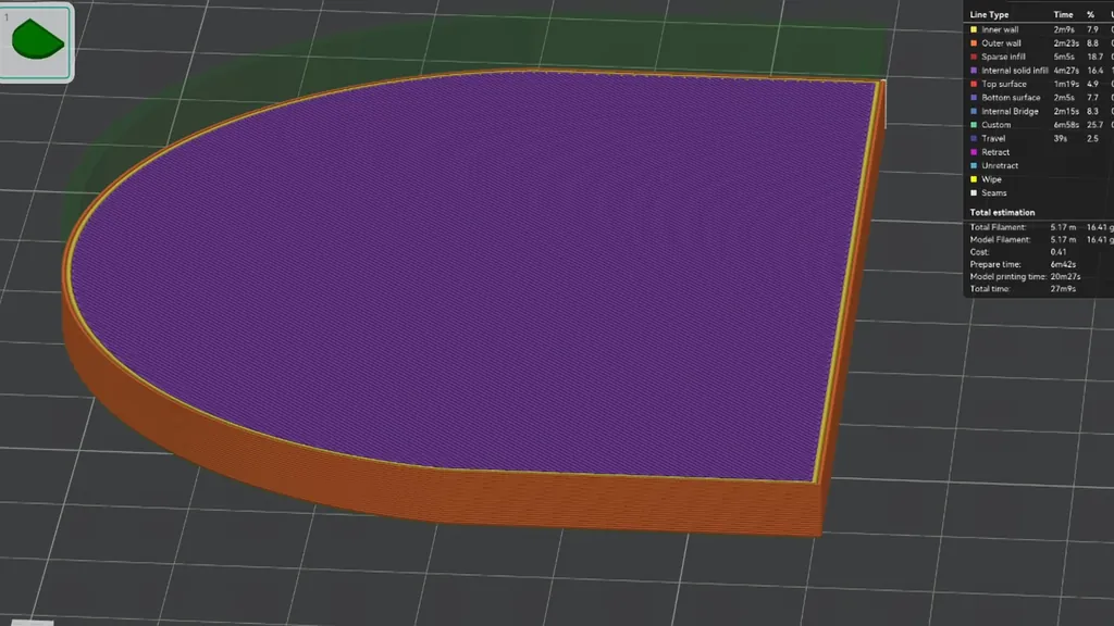
I started by printing a simple box lid using a standard 0.2 mm layer height profile. I kept my wall count at two and used basic speed and acceleration settings to ensure the baseline was consistent. I made sure my filament was dry and calibrated for flow rate, as any variation here would ruin my diagnostic data. When I examined the result under studio lighting, I saw an ugly line on the outside wall exactly at the Z-height of the inner lid surface. This line is a classic artifact that occurs when the internal geometry changes the thermal mass of the print. By starting with a controlled test, I can isolate whether the issue is mechanical or purely related to material shrinkage.
Analyzing Layer Time Discrepancies
I opened the slicer preview and checked the layer times to see if there was a correlation with the defect. While the basic preview looked fine, selecting the layer time view revealed something suspicious. I noticed that the layers corresponding to the hull line were taking 10 to 15 times longer to print than the surrounding layers. This happens because the printer slows down to maintain quality on complex features, but that extra time allows more heat to soak into the part. I need to understand that layer time is a proxy for the volume of material being deposited. When the printer dwells on a layer, it changes the thermal profile of the entire section.
Testing Layer Time Uniformity
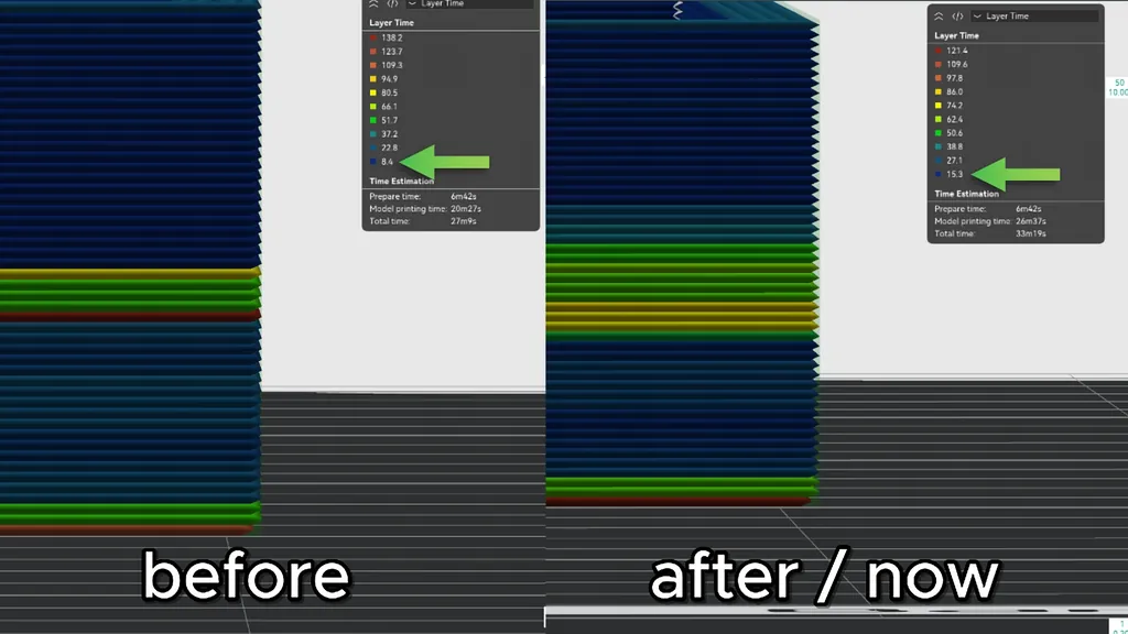
I attempted to smooth out the layer times by adding multiple height range modifiers to the problem section. I manually adjusted the speeds to force the printer to maintain a more consistent pace across the lid. However, the print result was actually slightly worse after these changes. I decided to push the issue further by setting the minimum layer time to 150 seconds in my filament settings. I also disabled the slow-down feature for outer walls to see if uniformity would help. This forced every layer to take between 150 and 165 seconds, yet the hull line remained stubbornly visible. It confirmed that simply adjusting speed won't fix the underlying shrinkage issue.
Identifying Shrinkage as the Root Cause
I realized the source of the problem is the material itself. When the plastic cools, it shrinks, and a larger volume of material creates greater shrinking forces that pull the connected walls inward. This inward pull is clearly visible when I print the design at 150% size, as the deformation becomes exaggerated. I also noticed slight bulging on the first bottom solid layers where the mass is concentrated. Shrinkage is a physical property of polymers, and when I have a transition from a solid floor to a thin wall, the differential cooling rates cause the wall to warp. This is why the hull line appears at the exact Z-height where the internal floor ends. I need to decouple these sections to prevent the solid mass from tugging on the outer perimeter.
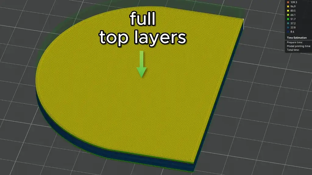
Implementing Decoupling Techniques
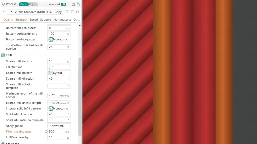
I started decoupling by increasing the thickness of the upper wall section, which creates a physical separation between the top layers and the walls. A close look at the preview showed a clear gap that prevents the top layers from pulling the wall inward during cooling. If I can't change the design, I reduce the top and infill overlap for the walls from the standard 15% to zero. I have to be careful here, because setting the overlap to zero or a negative value will weaken the part's structural integrity. This gap acts as a mechanical break in the cooling stress path, allowing the walls to shrink independently of the internal solid mass.
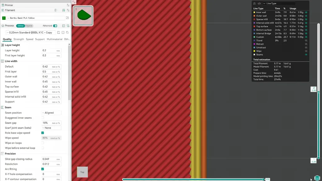
Comparing Decoupling Solutions
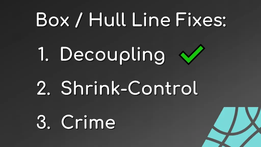
I compared three different decoupling solutions to see which one performed best in real life. The design solution with the biggest gap provided the cleanest result, as it completely eliminates the connection between the floor and the wall. The overlap solution showed slight improvement on the lower section, but it wasn't as effective as the geometric change. I also tested an upper wall gap solution that leaves a small connection at the very top. I found that the design-based approach is the most robust because it doesn't rely on slicer settings that might change with different print profiles. I prefer a clean, physical gap over trying to trick the slicer into ignoring the connection.
Optimizing Wall Printing Order
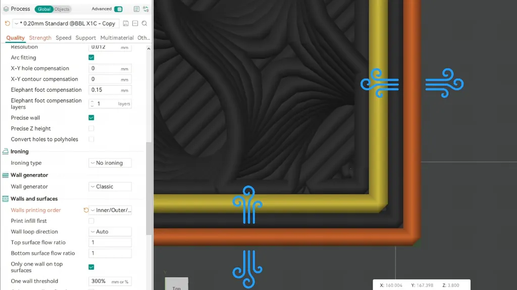
I set my wall printing order to inner-outer-inner to see if it would improve the outer wall precision. By printing the outer wall without other walls next to it, I achieved more symmetrical cooling and shrinkage from all sides. I noticed a clear improvement in the print quality, but I had to be careful. When I print with only two walls, this order change can lead to more visible seams because of the automatic switch in the printing sequence. I also activated the precise wall setting, which reduces the overlap for outer walls and provides a slight decoupling effect. This is a great alternative if I don't want to change the entire wall printing order.
Using CAD for Design Decoupling
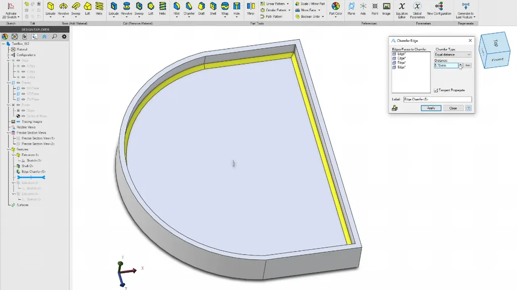
I used my CAD software, Alibre, to add chamfers to all the floor edges of my design. The bigger the chamfer, the more I decouple the solid floor from the outer wall. After printing this version, I saw that the top layers were no longer connected to the walls, resulting in a very clean finish. I've been using Alibre for several months, and the direct step editing features make these kinds of design tweaks incredibly fast. It's much more stable than other software I've used in the past. By modifying the CAD model, I'm addressing the root cause rather than just applying a band-aid in the slicer settings.
Controlling Shrinkage with Cooling
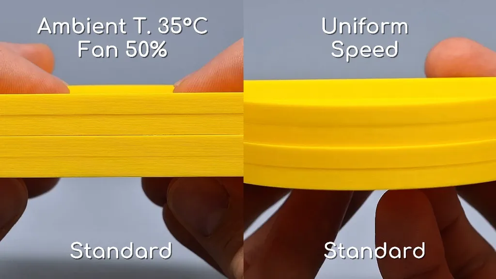
I moved on to shrink control, as my tests show that fast material cooling leads to the best results for reducing the box line. I set my cooling fan speed to 100% for PLA, which works best with my printer. I also keep the ambient temperature low and leave the chamber open to prevent the material from staying soft for too long. I have to be careful with materials like ABS, though, as they will warp if I cool them too quickly. Fast cooling locks the material in place before the shrinking forces can pull the walls inward. This is a simple but effective way to manage the thermal contraction of the plastic.
Achieving Uniform Print Speeds
I discovered that uniform print speeds are a major quality improvement. I set everything to match the outer wall speed, which results in more even flow and shrinkage across the entire part. This test also explained why my previous layer-time-adjusted print failed; the speed and flow were all over the place, which led to uneven shrinkage. By keeping the speed constant, I ensure the extrusion pressure remains steady. If I combine these uniform speeds with my decoupling techniques, the print quality improves significantly. It's clear that the consistency of the print process is just as important as the thermal management of the part.
Refining Functional Edges
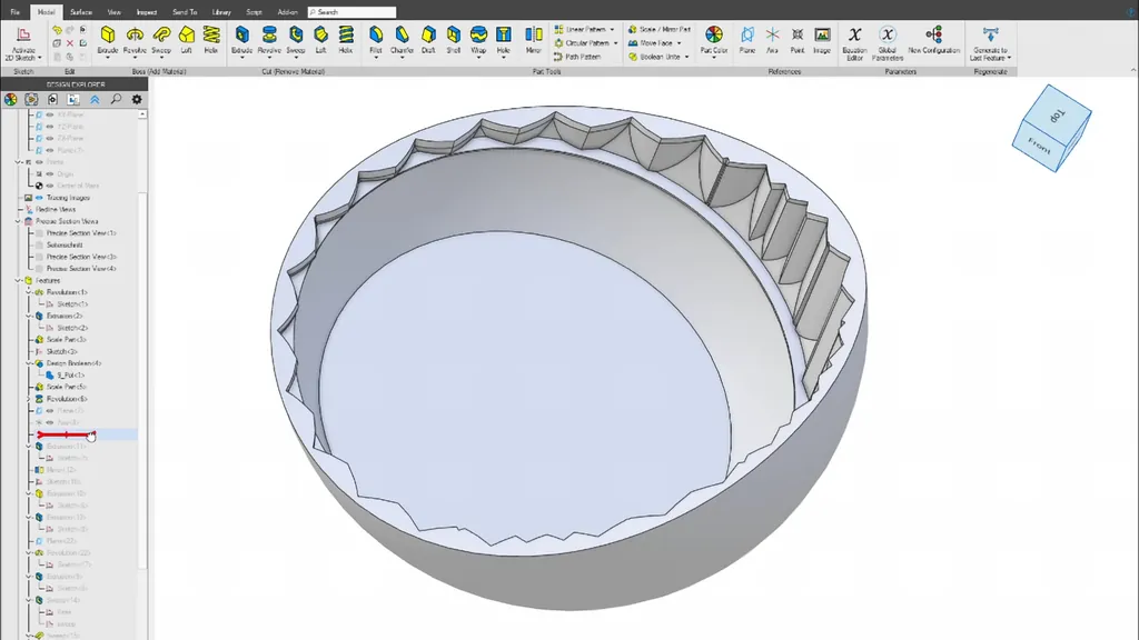
I found that most functional edges can be changed to smaller sections to control shrinking forces. Even with standard settings, this small change resulted in no hull line and clean outer walls. If I want to get extra fancy, I can reduce the flat lid surface by using a single loft operation in my CAD software. This allows me to curve the wall section and minimize the large flat areas that typically cause the most shrinkage. By reducing the surface area of the floor, I'm reducing the total force that can pull on the walls. It's a subtle design change that makes a massive difference in the final print quality.
Adjusting Vertical Shell Thickness
I turned off the ensure vertical shell thickness setting to prevent unwanted wall connections. This is highly design-dependent, but it helps in cases where the slicer tries to bridge gaps that I want to keep open. I also experimented with changing the skin expand distance and using low-stress infill patterns, though the latter never helped in my tests. What does help is being intentional about how the slicer connects the internal geometry to the shell. By disabling automatic shell thickening, I regain control over the physical gaps that prevent the hull line from forming. It's all about keeping the design features distinct from the structural walls.
Hiding Artifacts with Fuzzy Skin
I decided to try hiding the crimes when I couldn't fully remove the floor line. I added fuzzy skin to the model, which makes the most difference in the overall appearance of the part. I can paint this effect onto specific sections or use modifiers to target only the problematic areas. The test print showed that the more fuzziness I add, the more effectively I can hide the hull line. It's a simple trick, but it works well for parts that don't need a perfectly smooth finish. The texture masks the inward pull, making the defect look like a deliberate design choice.
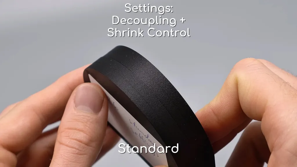
Using Chamfers and Fillets to Confuse
I moved the floor down so that only solid layers connect to the print plate, which I know reduces the shrinking problem. Then I added a chamfer followed by a fillet on the upper edge to confuse the eye. I did the same process on a large box and increased the fillet size. Before the change, the hull line was visible, but after adding the fillet, the box looked absolutely perfect. The fillet creates a gradual transition that masks the abrupt change in mass. My brain somehow interprets the inward pull as part of the intended curve, which is a great way to hide the defect.
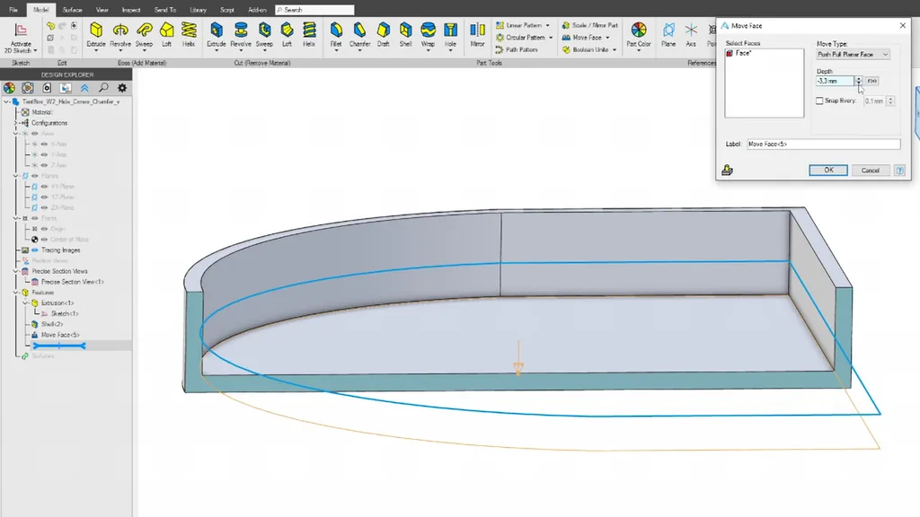
Finalizing Design for Clean Prints
I've found that for nearly all my planter and vase designs, angling or curving the base is the best way to avoid the box line. Even with basic print profiles, these shapes show no defects because there are no sudden transitions in mass. All the example models I've created are now linked for anyone who wants to test these techniques. I've spent a lot of time refining these methods, and they've significantly improved the consistency of my prints. If you're dealing with stubborn hull lines, try these design changes first. It's much easier to design around the problem than to fight the slicer for every single print.
⚠️ CAUTION: SAFETY WARNING!
Always ensure your printer is in a well-ventilated area when printing with materials like ABS to avoid inhaling fumes. Be cautious when handling hot prints or using sharp tools to modify your models.
Summary & Tips
I've successfully eliminated the hull line issue by combining design-level decoupling with strategic slicer adjustments. By adding chamfers and fillets, I've managed to hide the remaining artifacts that were previously ruining my box lids. These techniques have allowed me to achieve clean outer walls across all my designs. I'm now able to print complex shapes without worrying about those ugly horizontal lines appearing on the surface.
📋 FAQ
❓ Does this fix work for all 3D printers?
Yes, these techniques are based on the physics of material shrinkage, which applies to all FDM machines. Whether you use a bed slinger or a coreXY printer, the underlying cause of the hull line remains the same. You can apply these slicer and design changes regardless of your specific hardware.
❓ Is fuzzy skin the best way to hide lines?
It is a very effective way to mask artifacts, but it changes the texture of the entire part. I only use it when a smooth finish isn't required for the final application.
❓ Why do chamfers help with decoupling?
Chamfers create a gradual transition in mass, which prevents the sudden change in thermal contraction that causes the hull line. By spreading the mass change over several layers, the shrinking forces are distributed more evenly. This prevents the sharp inward pull that typically creates a visible defect on the outer wall.
❓ Can I use these fixes in any slicer?
Most of these settings, like wall printing order and overlap adjustments, are available in all major slicers like Cura, PrusaSlicer, and Bambu Studio. While I used Orca Slicer for this tutorial, the logic remains consistent across all platforms. You should have no trouble finding the equivalent settings in your preferred software.
Disclaimer: I purchased all tools for this guide with my own money to ensure an unbiased review. This post contains affiliate links, meaning I earn a small commission if you make a purchase at no extra cost to you.