Running flexible LED tape around sharp television corners leaves bunched, lifted edges that inevitably release from the plastic bezel within a month. Sticking a single run along the upper edge leaves patchy, lopsided bias lighting and looks amateurish. I route these backlights with dedicated 90-degree four-pin right-angle couplers, locking the exposed copper pads straight under spring-steel contacts. That setup yields a uniform perimeter cast without placing mechanical stress on the printed circuit board.
⚡ Quick Guide: How to Make It in 10 Steps
- Unbox the strip, controller, and remote.
- Locate scissor symbols and cut strip.
- Peel back adhesive tape and coating.
- Clear copper pads using utility blade.
- Pop open latch on corner connector.
- Seat conductors under metal contact pins.
- Match positive polarities across corner boards.
- Mount perimeter run around TV frame.
- Power via USB and test colors.
- Verify solid joint seating and mounting.
📋 In This Article
- Technical Specifications & Components
- Tools & Materials Used — what you will need for this project
- Unboxing the 5V LED Backlight Hardware
- Sizing the Top Run and Locating Cut Lines
- Exposing the Four Copper Conductors
- Trimming Factory Silicone and Adhesive Backing
- Opening the L-Shaped Corner Connectors
- Seating the Strip and Clamping the Terminals
- Matching Polarity on the Right-Angle Board
- Routing the Four-Sided Television Perimeter
- Powering the Array via 5V USB Source
- Final Inspection and Trace Continuity Check
- FAQ
📊 Technical Specifications & Components
| Input Voltage | DC 5V |
| Current Draw Rating | Up to 3.0A USB load |
| Total Strip Length | 118 inches (approx. 3 meters) |
| USB Controller Harness Length | 39 inches |
| Remote Control Protocol | 17-Key RF Wireless (433MHz / 2.4GHz) |
| Remote Effective Range | Up to 49 feet (non-line-of-sight) |
| Color Modes | 20 static colors, 20 dynamic speed cycles |
| Conductor Pitch & Count | 4-pin copper contact layout (+5V, R, G, B) |
| Adhesive Backing | Thick automotive-grade 3M adhesive tape |
| Waterproofing | Clear flexible silicone top coating |
📊 Project Overview & Costs
🔧 Difficulty Level: Low (basic hand trimming and terminal seating)
⏱️ Time Investment: DIY: 35-45 minutes | Professional: 15-20 minutes
💰 Professional Service Cost: $75 - $120 (standard audio-video bench rate)
💡 Verdict: Avoids $75 to $120 professional installation charges by using $20 in modular components and hand assembly.
🛠️ Tools & Materials Used
• Precision workshop shears, stainless steel blade
• Flexible RGB LED light strip kit, DC 5V, 118-inch total length
• 90-degree 4-pin solderless corner snap couplers, 10mm width
• Radio-frequency handheld remote control transmitter, 17-key layout
• Inline DC 5V USB power receiver and controller module
Step-by-Step Guide
Unboxing the 5V LED Backlight Hardware
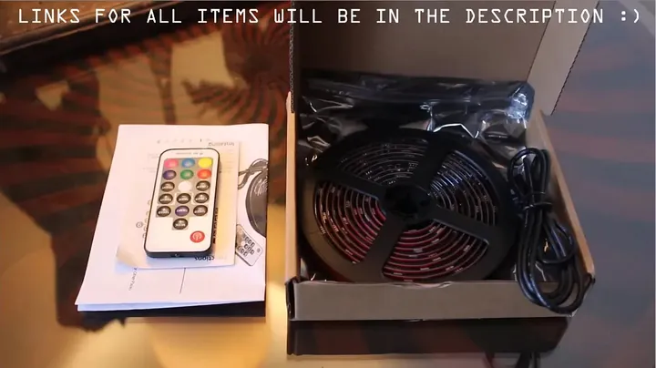
I started by spreading every component across the workbench to verify the hardware prior to stripping off protective tape. The package includes a 118-inch flexible RGB printed tape wound onto a plastic spool, a compact DC 5V inline USB controller harness, and a handheld 17-key RF remote transmitter. RF hardware outperforms standard infrared remotes on television setups because the signal punches straight through plastic panels without direct line-of-sight. The receiver cycles through twenty static shades along with dynamic automated fade patterns at distances reaching forty-nine feet. I checked the flexible ribbon under the bench lamp. Automotive-grade 3M adhesive backing runs along the full length of the bottom surface. Clean hardware.
Sizing the Top Run and Locating Cut Lines
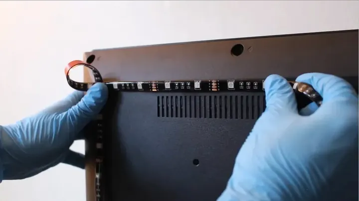
I pulled a measurement across the rear television bezel to establish the exact length required for the top horizontal run. Never fold flexible LED tape at sharp right angles across chassis corners. Creasing the ribbon tears the internal printed copper paths every time. I tracked down the length of the ribbon until I located the factory scissor graphic centered between duplicate copper contact points. I brought down the shop shears squarely through the midline of those paired copper lands with a single perpendicular cut. That worked. Centering the blade guarantees that both the severed segment and the active reel keep enough copper surface area to seat properly beneath the terminal fingers.
Exposing the Four Copper Conductors
I held the cut edge directly under the task lamp to examine the bare terminal traces. Four individual conductor paths run parallel down the tape: positive 5V power, followed by dedicated ground rails for red, green, and blue diodes. The manufacturer blankets the top components under a thick silicone waterproof jacket while applying adhesive foam across the bottom substrate. That rubber layer insulates the conductors and prevents mechanical continuity inside solderless terminals. I peeled away roughly a quarter-inch of the brown paper backing from the bottom corner. Then I made a shallow incision into the clear silicone skin directly above the copper lands without digging into the underlying copper foil.
Trimming Factory Silicone and Adhesive Backing
I took a sharp utility razor and scraped the remaining clear resin off the four conductive pads. Factory silicone leaves behind an invisible film that insulates the circuit and ruins electrical continuity inside mechanical terminal clasps. I held the blade flat against the fiberglass board so the edge wouldn't slice through the thin metal pads. Clean copper. With the top faces bare, I trimmed away the thick foam adhesive layer directly beneath that quarter-inch segment of copper tongues. Leaving that spongy tape attached doubles the ribbon thickness, preventing the strip from sliding into the tight entry slot of the plastic corner coupler.
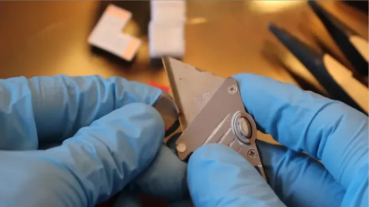
Opening the L-Shaped Corner Connectors
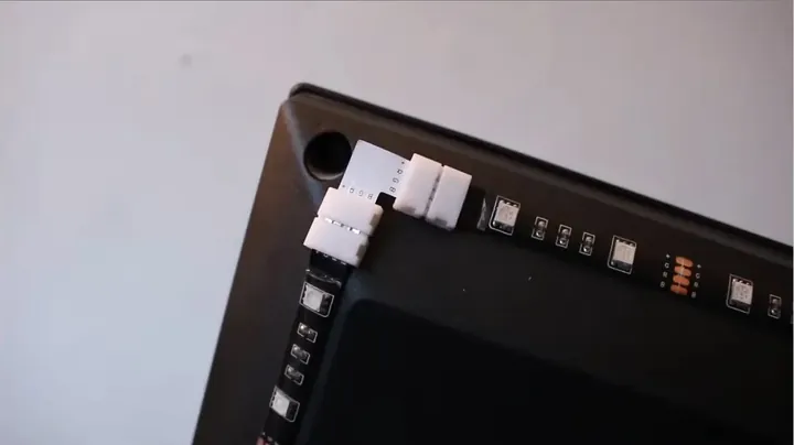
I pried open the hinged plastic latch on the L-shaped corner adapter. A small printed circuit board sits inside the housing beneath spring-steel terminal fingers. The clamp uses downward-facing metal teeth engineered to bite straight into the copper pads under mechanical pressure. I lifted the locking cover until the retention tabs released with an audible click. Forcing the hinge past its natural stop will snap the brittle plastic ears clean off. Once open, internal alignment ribs become visible, designed to center the 10mm ribbon over the four contact strips.
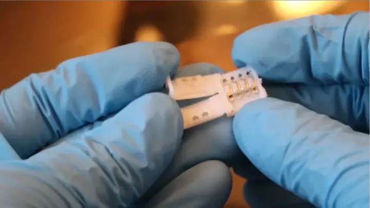
Seating the Strip and Clamping the Terminals
I pushed the prepared end of the LED ribbon into the narrow guide channel until the exposed copper landed directly beneath the spring clips. If the strip jams midway, residual adhesive on the underside is likely hanging up on the internal plastic lip. I pressed the copper lands flat onto the connector floor. I used the tip of a flat blade to press each spring contact down onto its matching copper pad. Manual pre-tensioning prevents high-resistance joints that lead to erratic flickering and dead color channels down the line. Firm pressure. I snapped the hinged plastic cover shut until the retaining catches locked tight.
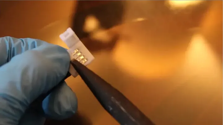
Matching Polarity on the Right-Angle Board
Trace orientation demands close attention before locking the perpendicular side into place. The mini circuit board inside the corner coupler has four discrete tracks silkscreened with +5V, R, G, and B markings. The markings must match identically across the joint. I aligned the positive voltage rail directly with the positive terminal on the incoming board. Flipping the orientation directs 5V straight into a color ground trace, which kills illumination across the entire downstream perimeter run. I slid the next section of tape beneath the secondary clamping jaws and latched the outer cover until it clicked. That creates a solid 90-degree corner joint that transfers full current around the television frame without bunched tape.
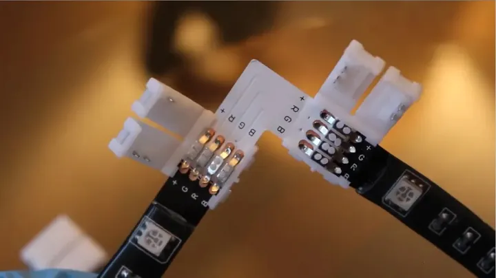
Routing the Four-Sided Television Perimeter
I routed the ribbon methodically around the plastic perimeter of the television cabinet. I stripped off the 3M release liner in two-foot sections, pressing the exposed tape firmly against the degreased television housing. I started near the USB service port where the inline receiver sits, routed up the left vertical edge, tied into the first corner coupler, traversed the upper span, ran down the right flank, and closed the loop across the bottom. Snug fit. Installing tailored strip segments connected by right-angle couplers keeps the assembly flush against the chassis, eliminating drooping tape and uneven illumination.
Powering the Array via 5V USB Source
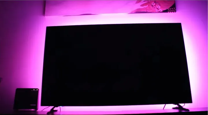
I connected the USB power lead directly into the rear service port of the television. Standard television ports supply 5V DC, but driving an extended ribbon on solid white output can pull two to three amps of current. When an onboard port drops voltage or strobes under full load, an external 5V charging brick clears up the issue immediately. I took the RF remote control and pressed the power button. A steady wall of diffused backlighting instantly washed across the drywall behind the display. Toggling through pure red, green, and blue verified solid continuity across every trace on all four corner couplers.
Final Inspection and Trace Continuity Check
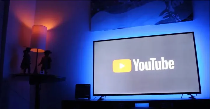
I stepped through multiple solid hues and dynamic transitions to confirm there were no dead sections or intermittent dropouts at the joints. If an isolated run displays yellow while the rest of the array renders clean white, the blue return trace on an adjacent corner coupler has lost connection. I gave each plastic junction housing a light finger tap to check for vibration sensitivity and loose contact fingers. Solid joint. The balanced bias lighting spreads evenly across the rear wall, reducing eye strain during high-contrast evening watching while giving the installation a clean factory appearance.
⚠️ CAUTION: SAFETY WARNING!
Disconnect USB power source prior to cutting ribbon substrates or manipulating exposed copper contacts inside corner connectors to prevent short circuits on the DC 5V rail.
Summary & Tips
Mounting a full four-sided LED bias lighting array changes television viewing by softening the extreme contrast between bright screen panels and dark ambient rooms. Spending twenty additional minutes cutting tailored strips and seating rigid right-angle couplers prevents the sagging and bunched corners caused by bending continuous tape. Solderless snap brackets keep this entire modification straightforward on an everyday workbench without heating up a soldering iron. Proper execution. The finished backlight looks like an integrated factory package rather than an aftermarket add-on.
📋 FAQ
❓ Power Supply: Capability of integrated television USB port to operate backlight array
Standard flat-screen displays feature at least one 5V USB output capable of supplying low-voltage accessory lighting. Factory service ports frequently limit current delivery to 500mA or 1.0A, which falls below the demand of a 118-inch RGB array set to maximum white output. Underpowered arrays exhibit flickering, random microcontroller reboots, or reduced output levels, requiring connection to a dedicated 5V 2.0A external USB power supply. External wall power provides regulated DC current across the entire four-sided perimeter.
❓ Fault Diagnosis: Downstream LED strip segment displaying incorrect color output
A color discrepancy on downstream segments indicates reversed polarity across an L-shaped corner adapter interface. The four conductive traces route positive 5V potential alongside discrete return lines for red, green, and blue color channels. Inverting the ribbon orientation or misaligning terminal channels within the clamping shell energizes incorrect diode circuits along subsequent spans. Reopening the connector housing and aligning the +5V reference rails across both adjoining boards resolves trace misalignment.
❓ Preparation Requirement: Necessity of stripping silicone coating prior to clamping
Silicone removal is mandatory for reliable mechanical connection. Solderless snap connectors require direct conductive engagement between spring-steel contact pins and bare copper pads. Retaining the factory waterproof coating causes terminal clips to rest on top of non-conductive clear insulation, breaking circuit continuity. Slicing away silicone material with a shallow blade pass exposes bare copper lands for positive clamping contact.
❓ Mechanical Routing: Feasibility of folding flexible ribbon versus right-angle connectors
Bending flexible printed circuits at ninety-degree chassis turns risks trace fracture and premature circuit failure. Internal copper conductive ribbons possess minimal thickness and suffer metal fatigue under mechanical pinching or acute creasing. Thermal cycling subsequently causes bent ribbon sections to lift off television bezels, generating uneven optical throw against backing walls. Rigid 90-degree corner couplers maintain planar alignment across all edges.
❓ Optical Mechanics: Mechanism by which bias backlighting reduces visual fatigue
Viewing high-luminance displays within darkened rooms induces rapid iris muscle contraction and dilation corresponding to scene luminance shifts. Bias lighting projects a calibrated ambient halo onto the wall plane behind the display chassis. This consistent reference illumination stabilizes pupil diameter, lowering ocular strain and fatigue during prolonged viewing intervals.
Disclosure: Hardware evaluated in this guide was acquired via independent procurement to maintain objective technical assessment. Content includes affiliate referral links generating operational commissions without altering retail consumer pricing.