
I see this fault in the shop all the time: a Samsung television powers up, relays click, and clean audio feeds through the speakers, yet the display stays pitch black. Most owners assume the panel or main logic board fried, but nine times out of ten the culprit is an open circuit along the LED backlight string. I dismantled the chassis, pulled the layers down to bare metal, and swapped the dead diode strips without cracking the wafer-thin liquid crystal matrix.
⚡ Quick Guide: How to Make It in 14 Steps
- Test the screen using a flashlight
- Map out screw and cable locations
- Inspect the internal power supply board
- Expose internal electronic assemblies
- Disconnect all internal panel cables
- Secure the circuit boards with tape
- Position the new LED backlight strips
- Reattach the plastic TV back cover
- Secure the main logic board connections
- Inspect internal circuit board traces
- Plug in and test screen backlight
- Check internal ribbon cable connections
- Review professional service safety limits
- Run final post-repair display checks
📋 In This Article
- Technical Specifications & Components
- Tools & Materials Used — what you will need for this project
- How to Diagnose Samsung Backlight Failure
- Mapping Screws and Cable Routes
- Inspecting the Power Supply Board
- Exposing Internal Circuitry
- Disconnecting Internal Wiring Harnesses
- Securing Circuit Boards with Tape
- Installing New LED Backlight Strips
- Reassembling the TV Back Cover
- Securing Main Board Connections
- Inspecting Board Traces and Solder Joints
- Testing the Screen Backlight
- Checking Internal Ribbon Connectors
- Professional Service Limits
- Running Final Post-Repair Checks
- FAQ
📊 Technical Specifications & Components
| Brand | Samsung |
| Compatible Models | UE32ES6100W, UE32ES6710, UE32ES6800, UE32ES6720S, UE32ES5500, UE32ES5507, UE32ES6760S |
| Failure Mode | Audio active, zero visible panel illumination |
| Diagnostic Method | External flashlight projection test |
| Primary Component | LED backlight module strips |
| Housing Type | Slim LCD television bezel and chassis |
| Power Supply | Internal AC-DC switched-mode power board |
| Matrix Type | Fragile thin-film transistor liquid crystal display |
📊 Project Overview & Costs
🔧 Difficulty Level: Advanced (requires delicate panel disassembly)
⏱️ Time Investment: DIY: 2 to 3 hours | Professional: 1 hour bench time
💰 Professional Service Cost: $180 to $250 (parts and labor included)
💡 Verdict: Component replacement saves substantial replacement expense when performed methodically on an anti-static surface.
🛠️ Tools & Materials Used
• Plastic pry tool, non-marring nylon
• High-output LED inspection flashlight
Step-by-Step Guide
How to Diagnose Samsung Backlight Failure
A baseline diagnostic was run before turning a single screw to confirm the panel was dark rather than dead. The set was powered on, the startup chime was awaited, and the speaker output was monitored. Good audio. A high-intensity flashlight was angled right against the glass surface about two inches away. Faint menu graphics moved underneath the dark glass, which confirmed the logic board and liquid crystal layer worked while the LED string remained dead. A precision bit driver set and a non-marring plastic wedge were brought out to unclip the perimeter. The main AC wall plug was pulled out completely before setting the panel flat on the padded bench. Mandatory safety step.

Mapping Screws and Cable Routes
Memory is never trusted when pulling modern electronics apart. Fastener positions were marked on low-tack painter tape, and every wiring route was logged with a phone camera before backing out any hardware. Samsung engineers mixed fine-thread machine screws with coarse-pitch self-tappers across the rear chassis and bezel bosses. Threading a long screw into a short corner socket will drive the tip straight into the back of the glass panel. Panel ruiner. Taking three minutes to lay out a magnetic hardware tray eliminates that risk entirely.

Inspecting the Power Supply Board
The switched-mode power supply board converts line voltage down to low-voltage DC rails for the logic processor and steps up the drive line for the backlight circuit. The electrolytic can capacitors were inspected under strong light, looking for domed metal vent tops, split sleeves, or crusty electrolyte dried on the circuit board substrate. A check was made for that distinct burnt-phenolic smell that signals an overheated diode or transformer winding. The chassis was powered with isolation probes, and the labeled DC pin voltages on the primary output header were checked with a digital multimeter. Care was taken to stay clear of the massive primary filter reservoir capacitor while running live checks. Serious bite there.

Exposing Internal Circuitry
The sheet-metal shields were lifted away from the central frame slowly to avoid bending the grounding tabs. The boards sit tucked flush inside molded plastic framework pockets with tight tolerances everywhere. Convection heat pulls an incredible amount of ambient dust and carpet fibers through these vents over thousands of operating hours. A soft-bristled brush along with a dry shop vacuum nozzle was used to pull the accumulated fuzz away before unseating any sensitive contacts. Clean workspace first. Thick gray grime covered the entire floorpan.

Disconnecting Internal Wiring Harnesses
The small side tabs on each wiring plug were compressed, and the connectors were drawn straight back without tilting the headers. Pulling at an off-angle will bend the microscopic terminal pins or crack the copper traces soldered into the board. When an aged plastic retention gate resisted, a fine nylon probe was used to ease the locking hook open. Cold plastic gets brittle with age, so forceful leverage was avoided. Steady pressure worked. A fractured retention bar causes intermittent signal dropouts and flickering lines on the panel later on.

Securing Circuit Boards with Tape
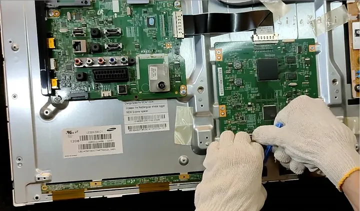
The loose driver boards and trailing ribbon leads were taped flat against the metal chassis with wide masking strips. The whole assembly had to be rolled face-up to work on the outer bezel retaining clips, and dangling circuit boards would flex the delicate chip-on-film ribbon interconnects. Lifting the raw LCD glass matrix out of its recessed seat demands absolute focus and steady hands. If you let the corner bind against the plastic channel, the sheet fractures into a web of broken glass instantly. Total scrap.
Installing New LED Backlight Strips
The fresh replacement LED strips were laid out side by side with the factory rails to verify connector pitch and lens spacing. Manufacturers use several incompatible strip configurations within the exact same model run, so visual matching is essential. The blue thermal tape backing was stripped away, and each aluminum extrusion was pressed firmly against the clean steel tub to ensure direct heat transfer. Every optical diffuser dome was wiped down with a clean microfiber towel to lift off stray fingerprints. Any smudge left on a plastic lens creates a persistent dim halo on white screens.

Reassembling the TV Back Cover
The rear plastic chassis shell was aligned square above the steel subframe and lowered into position. Thumbs were worked along the perimeter rim, snapping each molded clip into place until the seams closed tight. The perimeter fasteners were set back into their original locations using a hand driver rather than a power drill to avoid stripping the plastic threads. Light hand torque does the trick. That worked.

Securing Main Board Connections
Every multi-conductor harness between the main processor board and the power circuit was reconnected, referencing the teardown photos. A check was made that each flexible flat ribbon cable pushed squarely to its internal stop before pressing down the retention bail. A canted connector pin interrupts high-speed differential signaling and causes vertical colored lines across the screen. Every lock was checked twice with an inspection light. Solid connection.

Inspecting Board Traces and Solder Joints
The through-hole pins were scanned under magnification, searching for hairline stress rings, fractured pads, or crystallized solder fillets. The iron was heated to 350 degrees Celsius, fresh rosin-core solder was fed onto the suspicious transformer posts, and the alloy was reflowed. The flux plume smells acrid and irritates the nasal passages, so the extractor was kept running right beside the work. A solid joint cools to a mirror-bright concave wetting edge. Fractured joints trigger intermittent shutdowns as the circuit boards heat up.

Testing the Screen Backlight
The main power cord was plugged into an isolated bench outlet. The standby key on the remote handset was hit, and the white diffuser plate was verified to light up uniformly from edge to edge without dark patches. If a single strip remains unlit, cut the bench breaker instantly and verify DC drive polarity. Red feeds the positive rail, while black or white returns the negative leg. Full illumination.

Checking Internal Ribbon Connectors
A final inspection was run along the timing controller edge, and the LVDS cables were verified to seat parallel without caught insulation jackets. A single misaligned gold pin scrambles the high-speed timing data, throwing scrambled vertical color bands or static across the image. Each connector was pushed straight until the retention ears snapped in with an audible click. Snug fit.

Professional Service Limits
Large glass handling in commercial service departments relies on multi-cup vacuum lifting rigs and laminar-flow benches. If you tackle ultra-thin curved displays on an uneven bench without proper support jigs, the odds of shearing an edge rise fast. In this trade, you save some units and write off others. Know your limits before stressing an irreplaceable panel.

Running Final Post-Repair Checks
An external video test generator was patched into HDMI port one, and color saturation, edge brightness, and channel audio levels were verified. The panel was run on the bench under continuous load for forty-five minutes to confirm the driver circuit stayed cool under operating temperature. The display showed no hotspots, flicker, or banding. Back in service.

⚠️ CAUTION: SAFETY WARNING!
Safety Protocol: Disconnect main AC input and confirm zero-volt status on primary filter capacitors using a calibrated multimeter before handling internal power assemblies to prevent electric shock hazards.
Summary & Tips
Swapping out a failed backlight assembly restores a blank display for pennies compared to buying a replacement television. Focus stays entirely on how that bare glass sheet is handled, because one misaligned corner scraps the whole job. Fasteners are sorted by length in labeled trays as every chassis layer comes off. Clean panel reassembled with bright, balanced picture output.
📋 FAQ
❓ Why does my Samsung TV have sound but no picture?
Failure Mode: Open-circuit failure in series-wired LED backlight strips. Mainboard and audio amplification circuitry remain operational. Diagnostic confirmation: External illumination directed against panel surface reveals faint active video images beneath non-illuminated liquid crystal layer. Resolution: Complete backlight strip array replacement.
❓ Can I replace just one burnt LED or do I need a whole new strip?
Recommendation: Replacement of entire strip set. Individual diode replacement requires surface-mount soldering and yields high secondary failure rates due to equal operating hours across existing diodes. Full matched sets provide balanced forward voltage and uniform luminance.
❓ Is it hard to take apart the LCD screen matrix?
Assessment: High risk. Substrate thickness ranges from 1.0 to 1.5 millimeters without structural reinforcement once bezel is unclipped. Torsional stress or improper corner pressure results in non-repairable glass fractures. Flat, dust-free workbench and static-free suction handles required.
❓ How do I know which backlight kit to buy for my Samsung model?
Identification Method: Visual inspection of internal strip part numbers. Model stickers on rear chassis identify television model only. Chassis variants use differing panel vendors (AU Optronics, BOE, Samsung Display) across single model iterations with distinct connector layouts and diode counts.
❓ What tools do I need for this Samsung TV repair?
Required Tooling: Precision magnetic Phillips driver set (#0, #1, #2), non-marring plastic pry bars, digital multimeter (600V CAT III rated), padded anti-static work mat, and parts sorting bins for chassis hardware retention.
Disclosure: Hardware and tools evaluated were independently acquired. Affiliate referral links generate commission compensation without altering retail transaction costs.
