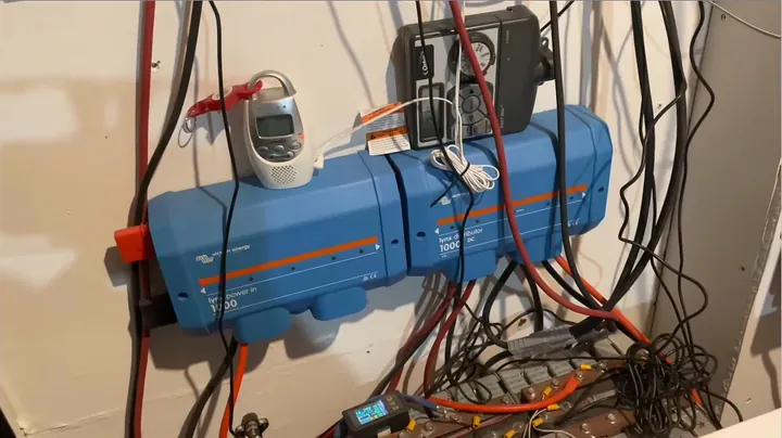
Modifying a factory Victron Lynx Power In Distributor adds integrated fusing for high-capacity off-grid setups. Standard units ship without internal fuse mounts, leaving internal busbars exposed to short circuits. Adding Mega fuses provides critical overcurrent protection directly inside the chassis, improving overall system safety.
⚡ Quick Guide: How to Make It in 15 Steps
- Disconnect the solar system safely.
- Prepare removed distributor and parts.
- Install mega fuses on busbar.
- Populate all fuse slots carefully.
- Understand distributor hack benefits.
- Address bolt length and washer issues.
- Verify fuse ratings by color.
- Plan for future channel expansion.
- Connecting the Inverter Cable.
- Torque all connections securely.
- Confirm fuses protect against shorts.
- Consider why all units need fuses.
- Energize MPPT, confirm fuse function.
- Reinstall plastic wire separators.
- Reviewing Hardware Limitations.
📋 In This Article
- Technical Specifications & Components
- Tools & Materials Used, what you will need for this project
- Disconnecting Solar System for Safety
- Preparing Removed Distributor and Parts
- Installing Mega Fuses onto the Busbar
- Populating All Fuse Slots Carefully
- Understanding the Distributor Hack Benefits
- Addressing Bolt Length and Washer Issues
- Verifying Fuse Ratings by Color
- Planning for Future Channel Expansion
- Attaching the Challenging Inverter Cable
- Torquing All Connections Securely
- Confirming Fuses Protect Against Shorts
- The Case for Distributors Over Power Ins
- Verifying MPPT Energization
- Reinstalling Plastic Wire Guides
- Final Reflections on Bolt Length and Nuts
- Frequently Asked Questions (FAQ)
📊 Technical Specifications & Components
| Fuse Rating (Inverter) | 250 Amps |
| Fuse Rating (MPPTs/Chargers) | 200 Amps |
| Bolt Size | M8 x 1.25, 25mm long |
| Nut Material | Stainless steel (304 vs 316 alloys) |
| Inverter Power | 2 Kilowatts (4 Kilowatt burst capability) |
| MPPT Controller Current | 60 Amps (max output) |
| Battery Type | Lead-acid (multiple in parallel) |
| Washer Material | Beryllium copper (split ring), regular steel |
| Bus Bar Material | Zinc-plated or copper |
📊 Project Overview & Costs
🔧 Difficulty Level: Medium
⏱️ Time Investment: DIY: 2-3 hours | Pro: 1 hour
💰 Professional Service Cost: $150-$300
This conversion provides essential fused protection, a feature missing from the stock unit.
🛠️ Tools & Materials Used
• Beryllium Copper Split Ring Washer
• Standard Washer
• M8 Nut
• M8 Bolt
• Mega Fuse
• Wrench
• Anderson connector
• Plastic wire guides
• Orange plastic screws
• Cable
• Victron Lynx Power In unit
• Victron Centaur charger
• MPPT controller
• Inverter
• Lead-acid batteries
Step-by-Step Guide
Disconnecting Solar System for Safety
Shut down all power completely before servicing high-current hardware. Disconnect the solar array from the Lynx Power In to eliminate residual voltage. Switch the inverter to shore power and verify that the solar panels generate zero current, preventing accidental exposure to high-wattage circuits.
Preparing Removed Distributor and Parts
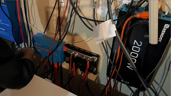
Attach the input and output cables directly to internal busbars using stainless steel M8 bolts, beryllium copper split-ring washers, standard steel washers, and M8 nuts. Organizing hardware on the workbench prevents misplacing small fasteners during assembly.
Installing Mega Fuses onto the Busbar
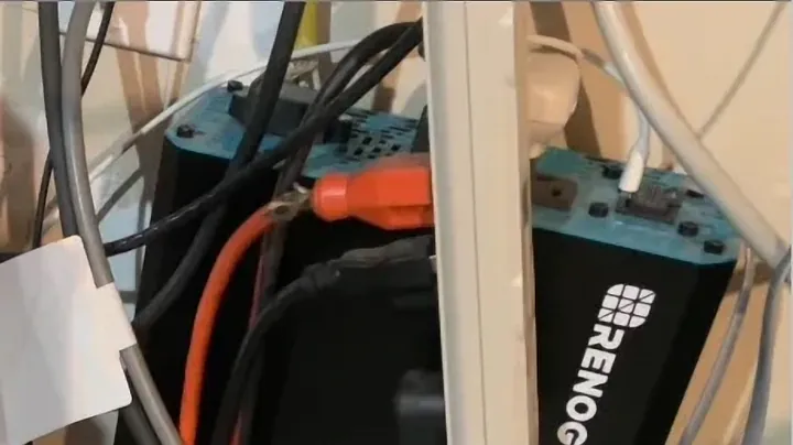
Mount Mega fuses directly on the internal busbars. Install a 250A fuse on the primary inverter channel to handle the 2kW load. Secure 200A protection across remaining channels reserved for MPPT charge controllers. While 60A controllers draw less current during routine operation, larger fuses protect supply conductors against direct shorts, ensuring adequate wire protection, while also standardizing hardware sizes.
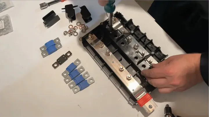
Populating All Fuse Slots Carefully
Populate all open positions after mounting the initial fuse. Position steel washers on both ends of each bolt to distribute clamping pressure evenly over the connection point. Proper alignment ensures low contact resistance, preventing localized heating under heavy current loads. Slide M8 hardware cleanly through the fuse terminals to avoid damaging threads.
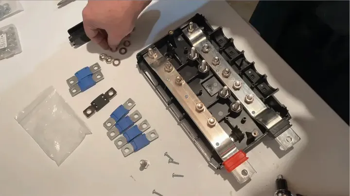
Understanding the Distributor Hack Benefits
Standard Victron Lynx Distributor modules feature a circuit board with blown-fuse indicator LEDs. Omitting active electronics when building a modified Victron Lynx Power In Distributor causes no operational loss in off-grid systems. Factory monitoring LEDs require an external battery monitor shunt. Skipping the indicator board creates a simple, reliable fused busbar at reduced cost.
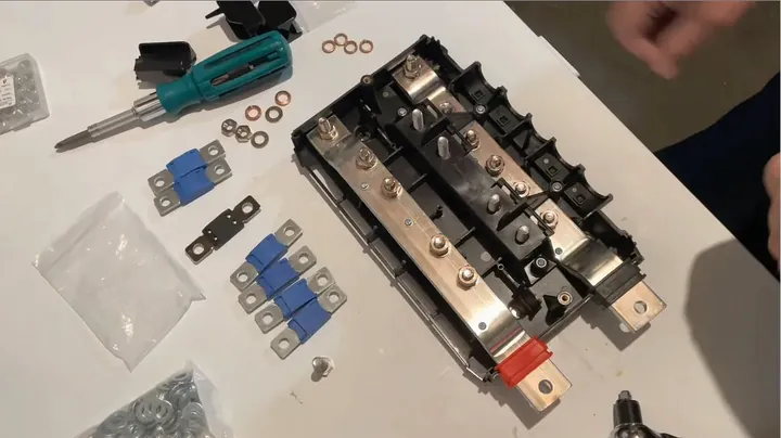
Addressing Bolt Length and Washer Issues
Stock M8 bolts may prove slightly short when stacking a mega fuse, multiple washers, and a split lock washer. Maximizing thread engagement ensures a resilient connection under continuous high DC loads. Removing one standard washer allows the nut to grip more threads when bolt length is restricted.
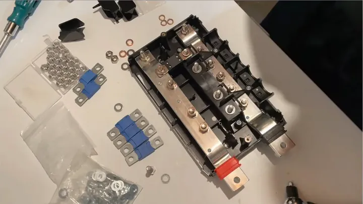
Verifying Fuse Ratings by Color
Confirm fuse ratings by reading the text stamped onto the blue plastic housing. Standard Mega fuses show 200 explicitly on the casing. Verifying physical components prevents assembly errors stemming from mislabeled product packaging.
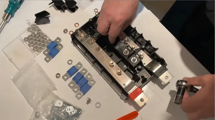
Planning for Future Channel Expansion
Modular Victron busbars simplify system expansion, allowing users to link extra blocks or utilize spare output positions. Direct contact between stainless steel, zinc-plated parts, and copper busbars promotes surface oxidation over extended service life.
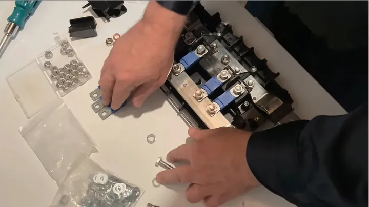
Attaching the Challenging Inverter Cable
Heavy inverter cabling poses the toughest assembly challenge. Large gauge copper resists bending, making terminal alignment difficult. Secure seating prevents resistance and voltage drop under high loads. Take time to position the lug flush against the terminal before tightening the hardware with a solid wrench.
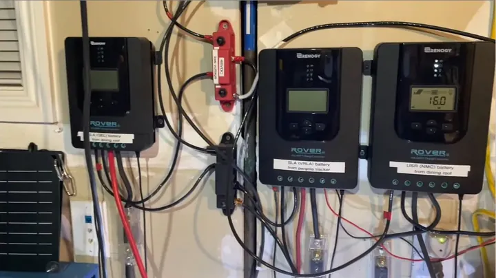
Torquing All Connections Securely
Torque all fasteners securely once components are properly aligned. Apply smooth force to avoid damaging the M8 threads. Proper wrench sizes ensure correct mechanical clamping at each joint. Tight connections eliminate contact resistance, heat buildup, and hardware failures in high-amperage DC systems.
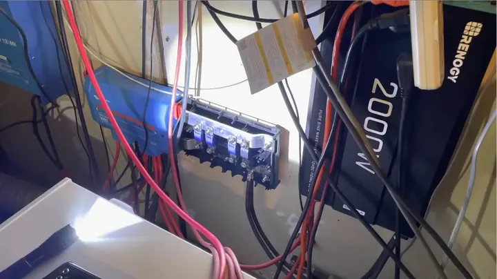
Confirming Fuses Protect Against Shorts
Overcurrent devices protect wiring rather than internal charge controller circuitry, including 200A units fitted to 60A MPPT channels. Controllers do not draw high currents during standard operation. Fuses mounted on the busbar isolate line shorts, opening instantly to prevent thermal damage or battery failure.
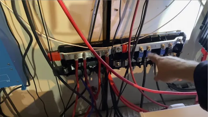
The Case for Distributors Over Power Ins
Unprotected power distribution hardware creates severe hazards in high-capacity battery setups. Every conductor running from a primary busbar requires dedicated fuse protection. Modifying a standard Power In chassis delivers essential circuit safety, which factory designs lack.
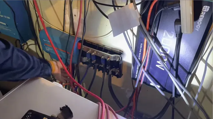
Verifying MPPT Energization
Re-energize the system after securing all connections and routing the conductors properly. With hardware properly seated, the MPPT controller powers up, indicating continuous current through the installed fuse. Successful illumination confirms the protective element remains intact and electrical continuity is established across the circuit.
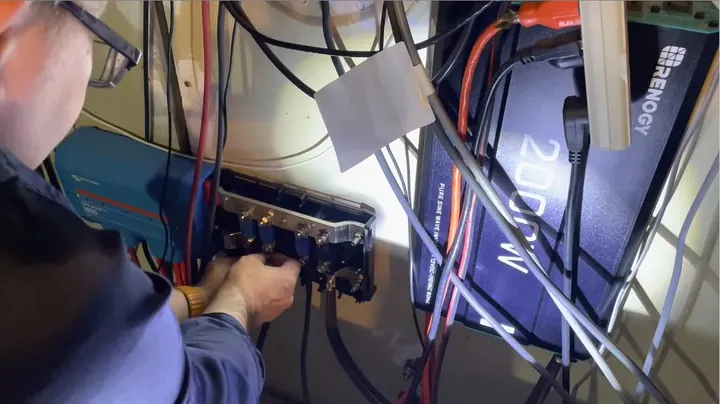
Reinstalling Plastic Wire Guides
Reinstall the black plastic wire guides next. Mounting these components requires loosening several chassis screws slightly. The guides create a physical barrier between adjacent power lines to isolate positive and negative cabling. Securing the covers completes the mechanical assembly phase.
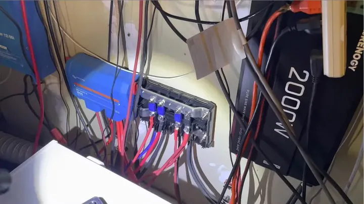
Final Reflections on Bolt Length and Nuts
Longer M8 bolts would simplify this conversion significantly. Stacking busbars, fuses, and washers quickly exhausts available thread length. Using low-profile M8 nuts provides additional thread engagement when space is limited. Modifying stock equipment requires adapting standard hardware to fit added components.
⚠️ CAUTION: SAFETY WARNING!
Disconnect all energy sources, including battery banks and solar arrays, prior to performing maintenance on high-amperage DC equipment. De-energizing the system prevents thermal events, electrical shock, and equipment damage.
Summary & Tips
Modifying the Victron Lynx Power In yields a fully fused distribution block for high-current setups. Installing M8 fasteners and Mega fuses adds essential protection to each output leg. This modified assembly isolates short circuits, safeguarding wiring and connected electronics from thermal damage.
📋 Frequently Asked Questions (FAQ)
❓ Why convert a Victron Lynx Power In to a distributor?
Protecting critical hardware drives this modification. Factory Lynx Power In modules feature un-fused busbars, leaving output lines vulnerable to ground faults. Installing Mega fuses transforms the stock enclosure into a protective distribution hub, clearing short circuits before extreme heat damages cabling or downstream gear.
❓ What fuse ratings should I use for this conversion?
Match fuse ratings directly to wire size and continuous electrical load demands. A 2kW inverter runs safely behind a 250A Mega fuse on the main busbar terminal. Branch circuits feeding 60A MPPT controllers accept 200A units, providing short-circuit protection while allowing future equipment expansion.
❓ Is the missing circuit board in the converted unit a problem?
Omitting the factory indicator board retains full circuit protection. Standard Lynx Distributors use an LED module to signal blown fuses, requiring an external Victron battery monitor shunt. Operating without this internal board maintains identical busbar functionality while eliminating extra electronic complexity.
❓ What about galvanic corrosion when mixing metal types?
Galvanic corrosion occurs whenever dissimilar metals meet in conductive environments. Standard stainless steel bolts reduce oxidation risks but can still react slowly with zinc-plated hardware or copper busbars over time.
❓ Why use 200-amp fuses for a 60-amp MPPT controller?
A 60A MPPT charge controller will not draw 200A under standard conditions. Placing a 200A fuse on that branch protects wiring against direct ground shorts. Higher-capacity fuses also allow swapping the controller for a compact inverter later without replacing existing busbar hardware.
Disclosure: this post contains affiliate links. If you buy through them, we may earn a small commission at no extra cost to you.