Expanding your energy storage capacity by integrating a 51.2V LiFePO4 server rack battery with a Pecron F5000 is a practical way to increase off-grid runtime. By measuring the expansion ports and fabricating a custom interface, you can safely bridge external chemistry to the power station’s internal management system. This procedure requires careful attention to wiring, circuit protection, and voltage matching to ensure the system functions as a unified power bank.
⚡ Quick Guide: How to Make It in 16 Steps
📋 In This Article
- Technical Specifications & Components
- Tools & Materials Used — what you will need for this project
- Verifying Expansion Port Voltage
- Fabricating Custom Interface Cables
- Initial System Power-Up
- Running a Full Capacity Test
- Monitoring Discharge Progress
- Analyzing System Cutoff
- Testing Charging Efficiency
- Evaluating Wiring Capacity
- Verifying High-Load Performance
- Importance of Inline Protection
- External Charging Observations
- Parallel Battery Configuration
- Confirming System Integration
- Adapter Cable Construction
- Stripping and Routing Wires
- Final Verdict on DIY Expansion
- FAQ
📊 Technical Specifications & Components
| Pecron F5000 Expansion Port Voltage | 54.64V |
| Battery Chemistry | LiFePO4 (LFP) |
| Battery Nominal Voltage | 51.2V |
| Battery Capacity | 100Ah |
| Wiring Gauge | 8 AWG |
| Connector Type | Anderson SB175 |
| Circuit Protection | 40A DC Breakers |
| Max Continuous Current per Port | 40A |
| System Max Current Capacity | 80A |
| Inverter Load Tested | 1,400W |
📊 Project Overview & Costs
🔧 Difficulty Level: Medium
⏱️ Time Investment: DIY: 2-3 hours | Pro: 1 hour
💰 Professional Service Cost: $600 - $1,200 depending on battery capacity
💡 Verdict: DIY expansion offers significantly more watt-hours per dollar compared to proprietary expansion packs.
🛠️ Tools & Materials Used
• 40 Amp DC Breakers
• Anderson SB175 Connector
• 4 AWG Wire Terminals
• Pecron Expansion Battery Cable
• Vatrer 51.2V 100Ah LiFePO4 Battery
Step-by-Step Assembly, Repair, Testing & Inspection
Verifying Expansion Port Voltage
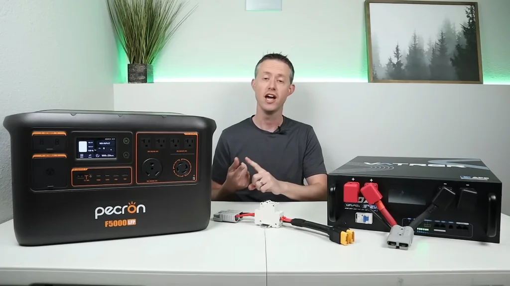
Before connecting any external hardware, you must confirm the compatibility of your power station's expansion ports. Grab your multimeter and set it to DC voltage mode. Turn the Pecron F5000 on and probe the expansion battery ports directly. You should see a live voltage reading, in this case, 54.64 volts. It's live. This confirms the ports are active and ready to accept an external DC source.
Fabricating Custom Interface Cables
You need to modify the factory expansion cables to include safety protection. I used 8-gauge wire which supports 40 amps of continuous current. I installed a 40-amp DC breaker on each positive line to prevent overcurrent events. The SB175 connector is my go-to for these high-power connections. It's robust. These breakers are non-polarized, allowing current to flow in both directions during charge and discharge cycles.
Initial System Power-Up
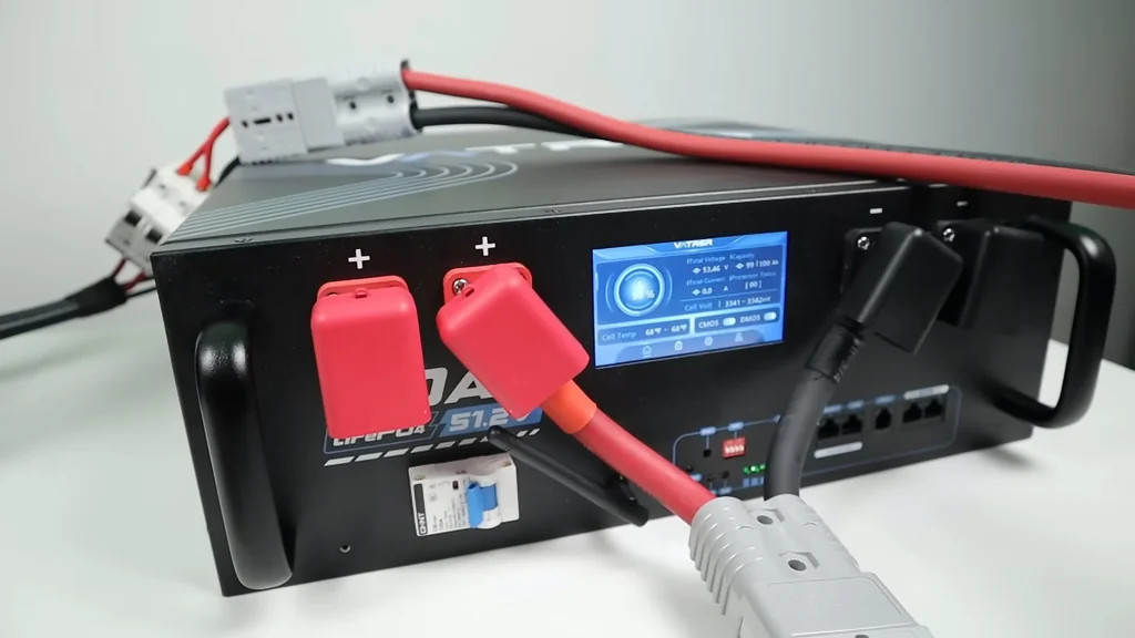
The Vatrer 100Ah server rack battery is a compact, smart unit with integrated Wi-Fi for remote monitoring. I've had good luck with these in the past. Flip the DC breakers to engage the connection. You will notice a brief inrush of current on the power station display as the capacitors charge. It's normal. Keep an eye on the screen to ensure the F5000 recognizes the external voltage without throwing an error code.
Running a Full Capacity Test
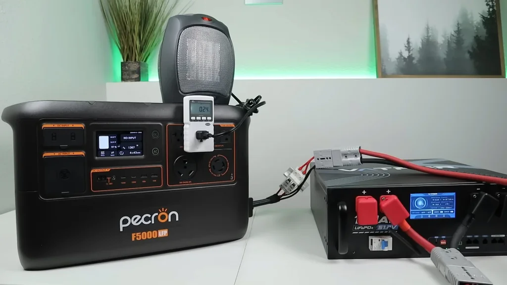
Now it's time to verify the usable capacity of the combined system. I connected a 1,500W heater to the AC output to pull a consistent load. The monitor shows it running at approximately 1,400W. It's pulling hard. We are tracking the energy output to see how much the external battery contributes to the total runtime. Everything looks stable so far.

Monitoring Discharge Progress
Checking the system halfway through the test reveals interesting data. The power station is at 50% state of charge, while the external battery sits at 61%. The discharge rate has shifted. We are seeing -13.7 amps coming from the external battery instead of the initial 10 amps. The load is drawing more heavily from the external pack as the internal cells deplete. It's working.
Analyzing System Cutoff
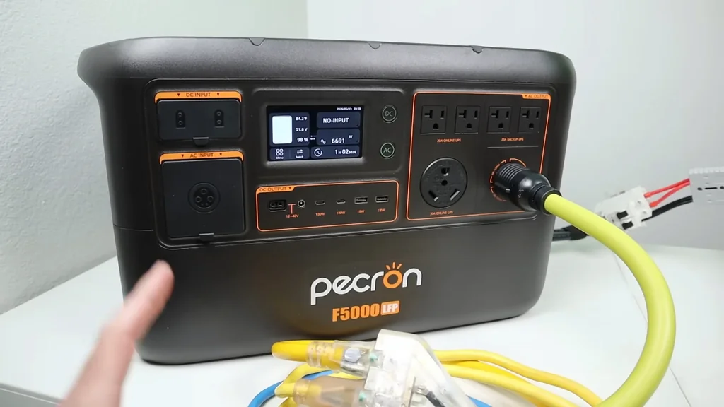
There is roughly a 10% difference in state of charge between the power station and the battery throughout the test. Once the F5000 shuts off, the external battery remains at 1% state of charge. The discharge MOSFET is still active. This indicates the battery still has a tiny bit of reserve capacity left. It's finished.
Testing Charging Efficiency
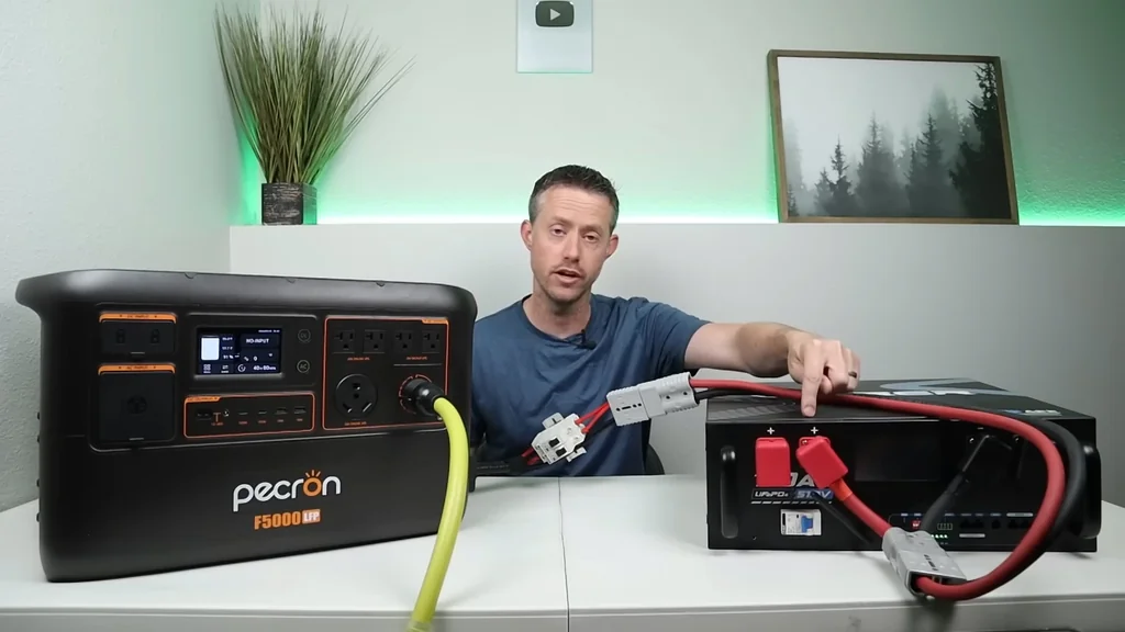
Charging the system back up is the final proof of concept. I applied over 1,000W of input power to the system. The calculation shows about 400W going directly into the external battery. Both the power station and the external battery reached 100% state of charge simultaneously. It's balanced. This confirms the external charger successfully manages the entire system.
Evaluating Wiring Capacity
Each expansion port uses 8-gauge wire rated for 40 amps. By using two of these ports, we achieve a total capacity of 80 amps. At 48V, that's roughly 4,000W of potential power. It's plenty. I want to ensure this setup remains safe under the maximum inverter load, so I'm testing the 240V 30A output.

Verifying High-Load Performance
Under a heavy load, we are pulling 49 amps. At 52 volts, that equates to approximately 2,400 watts. We have significant headroom since the wiring supports 80 amps. The battery handles a larger portion of the load as the state of charge drops. It's efficient.
Importance of Inline Protection
Using the correct breakers is non-negotiable. If an over-amperage event occurs, the breakers will trip to prevent the wires from melting. You cannot rely solely on the battery's internal BMS. Always size your breakers to match the wire gauge. It's safe.
External Charging Observations
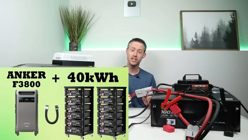
I connected a 48V 18A charger to the external battery to see if it charges the entire system. The power station screen shows no input, but the estimated time to full is decreasing. The BMS recognizes the charge, even if the F5000 doesn't display it as a direct input. It's charging.
Parallel Battery Configuration
You can connect multiple batteries in parallel to increase your total energy storage. Just ensure all batteries are at 100% state of charge before you link them. This prevents large current spikes between packs. It's critical. You can also add solar to the external battery, and it will combine with the system seamlessly.
Confirming System Integration
The F5000 performs reliably with DIY battery additions. My test shows the entire system charges and discharges as one unit. The external charger successfully brings everything to 100% state of charge. It's solid. The F5000 behaves just like it does with proprietary expansion packs.
Adapter Cable Construction
I terminated the adapter cable with an Anderson SB175 connector. This is a 175-amp rated connector, which is overkill for our 80-amp setup but provides excellent durability. I used 4-gauge wire terminals to crimp the two 8-gauge cables perfectly. It's a clean fit. The rest of the cable is standard Pecron accessory gear.
Stripping and Routing Wires
After stripping the rubber insulation, I found the main positive and negative leads along with several communication wires. I trimmed the communication wires since they aren't needed for this specific mod. I kept the positive and negative leads long to install the DC breakers in-line. It's organized. The negatives run as one piece, while each positive has its own breaker.
Final Verdict on DIY Expansion
Building these adapters is straightforward if you have the right tools. It only took a little bit of time to assemble. I've built many of these, and this method works well. It's exciting to use your own battery with the F5000. It works with other Pecron stations too.
⚠️ CAUTION: SAFETY WARNING!
Working with 51.2V lithium batteries involves high energy density and potential for arc flashes; always disconnect the battery before making wiring changes and use properly rated DC breakers.
Summary & Tips
Integrating a DIY battery with the Pecron F5000 significantly extends your usable off-grid power. The system functions reliably when wired with appropriate gauge cabling and circuit protection. Proper voltage matching and parallel connection techniques are essential for system longevity. This modification is a highly effective way to maximize your power station's utility.
📋 FAQ
❓ Can I use any 48V battery with the Pecron F5000?
Usually, you need a LiFePO4 battery that matches the voltage range of the expansion port. It's best to stick to 51.2V nominal packs. Always verify the port voltage before plugging anything in.
❓ Is it safe to connect batteries in parallel?
Yeah, it is safe if you ensure all batteries are at the same state of charge first. This prevents massive current surges between the packs. It's a standard procedure for off-grid setups.
❓ Why do I need DC breakers for this mod?
Honestly, they are for your protection. If a short circuit occurs, the breakers will trip and prevent the wires from melting. You can't rely on the battery's BMS alone.
❓ Does the Pecron F5000 show the external battery capacity?
Depends on the specific setup. Sometimes the BMS will recognize the charge, but the screen might not show the external battery percentage directly. You'll need to monitor the external battery separately.
Disclaimer: I purchased all tools for this guide with my own money to ensure an unbiased review. This post contains affiliate links, meaning I earn a small commission if you make a purchase at no extra cost to you.