Solving a Victron Lynx Shunt reverse current error requires looking inside the unit when you alter your power wall layout. Swapping the battery bank and distributor locations shortens heavy cable runs, but it flips current polarity on the internal PCB. Here is how to fix the state-of-charge readout by swapping internal sense wires safely.
⚡ Quick Guide: How to Fix Reverse Current in 10 Steps
- Isolate all solar, battery, and inverter breakers.
- Verify negative discharge reading on Cerbo GX display.
- Remove top plastic cover from Lynx Shunt enclosure.
- Identify sense wires connected across brass shunt resistor.
- Replicate current flow on lab bench using multimeter.
- Confirm polarity flip reading under simple light load.
- Unbolt terminal screws securing thin sense signal wires.
- Swap physical sense wire connections on shunt sides.
- Re-energize main battery isolation switches and solar panels.
- Confirm positive charging current on Cerbo GX display.
📋 In This Article
- Technical Specifications & Components
- Tools & Materials Used — what you will need for this project
- Rerouting Power Wall Components
- Identifying Current Polarity Reading Errors
- Inspecting the Exposed Shunt Assembly
- Tracing Internal Sense Wires and Auxiliary Power Taps
- Setting Up Lab Bench Simulation
- Simulating Polarity Inversion on the Bench
- Swapping Physical Shunt Sense Lines
- Re-routing Auxiliary Power and Fuse Detection Leads
- Re-energizing System Breakers and Inverter
- Verifying Correct State of Charge Monitoring
- FAQ
📊 Technical Specifications & Components
| Unit Type | Victron Energy Lynx Shunt VE.Can |
| Current Rating | 1000A Continuous DC |
| System Voltages | 12V / 24V / 48V DC Native Support |
| Measurement Principle | Millivolt drop across precision shunt resistor |
| Communication | VE.Can / NMEA 2000 |
| Monitor Interface | Victron Cerbo GX / Touch 50 Display |
| Auxiliary Sense Connections | Voltage tapping & Fuse blown detection |
📊 Project Overview & Costs
🔧 Difficulty Level: Medium
⏱️ Time Investment: DIY: 45 minutes | Pro: 20 minutes
💰 Professional Service Cost: $75
💡 Verdict: Saves you from buying expensive extra gauge battery cables or running messy cross-overs.
🛠️ Tools & Materials Used
• Victron Energy Lynx Shunt VE.Can
• Victron Energy Cerbo GX Monitor
• DC Rated Bi-Directional Circuit Breakers
Step-by-Step Guide
Rerouting Power Wall Components
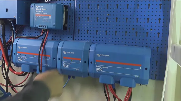
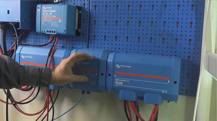
Swapping the Lynx Power In and Lynx Distributor modules on a off-grid power wall makes total sense when trying to cut down cable length. Originally, the battery bank connected on the left side while the load distribution panel hooked up on the right. Extending 2/0 or 4/0 AWG battery cables halfway across the board is expensive and creates unnecessary voltage drop. Flipping those modules left-to-right solved the physical wire routing immediately. It created a much cleaner layout. However, busbars inside the Victron Lynx Shunt are directional. Running current through the block backward flips the measurement across the internal sensing circuit.
Identifying Current Polarity Reading Errors
Checking the Cerbo GX display right after turning the system on revealed an obvious readout failure. Solar charge controllers were pushing solid current into the system, but the screen showed a negative current value. The system thought the battery bank was discharging instead of charging. State of charge percentages were dropping fast while full sun hit the solar array. That's wrong. A shunt works by measuring a minute millivolt drop across a known low-resistance copper-manganin block using Ohm's Law ($V = I \times R$). When physical current enters through the output busbar, the micro-voltmeter IC on the internal PCB reads a negative differential. The system must be shut down completely before performing internal modifications.
Inspecting the Exposed Shunt Assembly
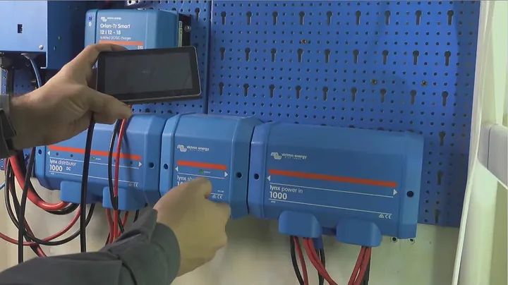
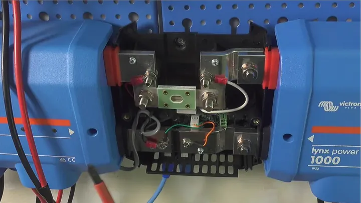
First, kill power everywhere. Disconnect the Victron MultiPlus inverter, isolate solar panel array breakers, and switch off all DC bi-directional circuit breakers feeding the main battery bank. Once the status LED turns off, remove the plastic front cover to expose the solid metal busbars. Inside sits a heavy precision shunt resistor spanning the main negative conductor path. Small gauge wire leads tap into brass posts on either side of the shunt block. These tiny sense wires feed the tiny differential voltage straight into the monitoring board. If current flows from right to left instead of left to right, the voltage polarity seen by those signal pins inverts completely.
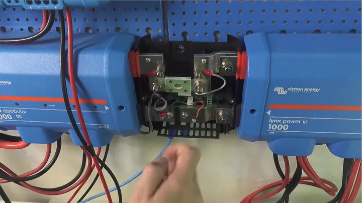
Tracing Internal Sense Wires and Auxiliary Power Taps
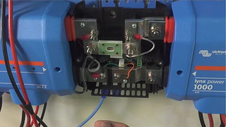
Taking a closer look at the internal wiring reveals four separate small conductors plugged into the electronic controller section. Two of these wires are raw voltage differential sense lines attached to the primary brass shunt. The other two serve specific jobs for system power tapping and blown fuse detection circuit ground. Here's the plan. We need to physically swap the sense line connections across the shunt terminals. On top of that, the auxiliary wire tapping positive power after the main fuse needs to be switched so the internal logic board remains powered off the correct battery side bus bar. It's straightforward. Just trace every thin wire before unfastening screw terminals.
Setting Up Lab Bench Simulation
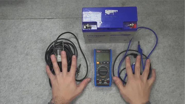
Before taking tools to an expensive $300 piece of Victron hardware, setting up a quick bench proof-of-concept proves the electrical theory. A simple test rig uses a small 12V lead-acid battery, a incandescent lamp load, and a standard digital multimeter set to DC amps mode. The multimeter's internal shunt works identical to the Lynx Shunt. Connecting red and black leads in series between the battery positive post and the light bulb completes the circuit. When leads are oriented naturally, current reads as a positive value on the meter.
Simulating Polarity Inversion on the Bench
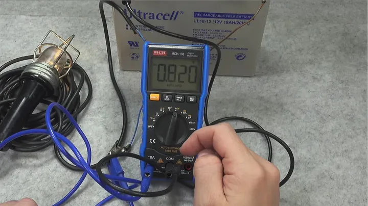
With the test circuit live, the multimeter shows roughly 0.820 Amps flowing through the light bulb filament. If this meter was the internal logic board of our power wall shunt, it would report healthy active charge or discharge current. It works. Now flip the multimeter probes in reverse while keeping current flowing in the exact same physical direction through the bulb. The display immediately jumps to negative -0.820 Amps. This proves that swapping sense wire leads trick the internal measurement IC into reversing its mathematical vector without changing main DC cable routing.
Swapping Physical Shunt Sense Lines
Back at the main power wall, confirm isolation once more with a voltmeter across the busbars. Zero volts. It is safe to work. Carefully loosen retaining screws holding the ring terminals on either end of the brass current shunt resistor. Take the wire originally sitting on the left sense post and move it over to the right terminal. Take the right sense wire and secure it onto the left post. Snug the screws back down firmly into brass, but don't over-torque them. Stripping those tiny threads ruins the unit.
Re-routing Auxiliary Power and Fuse Detection Leads
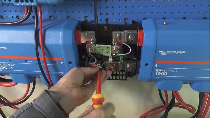
Next up are the auxiliary sensing and power supply leads running along the top rail. Unclip the thin red positive tap line feeding internal power from behind the main megafuse. Move this tap wire to the opposite post so it senses power downstream of the fused connection point properly. Route wires neatly along the bottom internal channel so they don't get pinched when snapping the main protective cover back on. Double check that no bare ring connectors touch adjacent metal chassis plates. It's solid.
Re-energizing System Breakers and Inverter
Reinstall the main outer faceplate on the Victron Lynx unit. Snap plastic side covers into position. Flip the primary DC battery disconnect switches back on to restore main busbar potential to the system. The green power LED on the Lynx Shunt turns on immediately. Next, switch solar PV isolator breakers on and flip the Victron MultiPlus back into 'Charger Only' mode. No sparks, no blown fuses, no magic smoke.
Verifying Correct State of Charge Monitoring
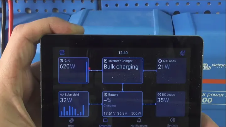
Head over to the Cerbo GX display screen and pull up the Device List overview. Navigate to the MultiPlus state menu and observe live system current metrics. As solar power feeds through the charge controller into the DC distributor, current registers as a clean positive amperage value. Everything works as intended. State of charge percentages now count upward during solar charging and show negative values only when running loads off battery power alone. That's the whole trick.
⚠️ CAUTION: SAFETY WARNING!
Always fully isolate high-current DC battery banks, solar PV arrays, and AC grid feeds before opening the Victron Lynx Shunt casing. Accidental busbar shorts will cause catastrophic arcing and equipment damage.
Summary & Tips
Modifying internal sense wires on the Victron Lynx Shunt easily fixes reverse current reading issues caused by flipped physical layouts. This modification avoids routing thick, expensive battery cables across your power wall board. Performing bench tests with a multimeter confirms polarity response before making changes on live systems. Always recheck terminal tightness and power taps to keep battery monitoring accurate.
📋 FAQ
❓ Why does the Victron Lynx Shunt read negative current while charging?
This happens when current enters through the output busbar rather than the designated battery side. If you swap distributor and battery bank locations on your power wall, current direction flips across the internal shunt block. The internal sensing circuit interprets positive voltage drops as negative current. Swapping signal sense lines corrects this display error.
❓ Will reversing internal sense wires void the Victron warranty?
Yeah, opening the enclosure and modifying internal factory wiring is not documented in standard Victron user manuals. It carries a risk of voiding your manufacturer warranty if components get damaged. However, electrically you are simply reversing signal probes without altering high-voltage power paths. Proceed at your own risk.
❓ Can I fix reverse current readings in software on the Cerbo GX?
Nah, Victron firmware does not currently offer a software toggle switch to invert current polarity on the Lynx Shunt VE.Can. The internal microprocessor hardware calculates vector state directly from differential millivolts on its sense pins. A physical wire swap is required to correct inverted SOC readings.
❓ Do I need to swap high-current busbars to reverse current flow?
Honestly, no. High-current copper busbars are solid metal conductors that carry amperage equally well in either direction. The issue is strictly how the internal sensing PCB measures differential voltage across the shunt. Leaving heavy busbars in place and swapping small sense wires saves time and money.
❓ What happens if I forget to move the auxiliary power tap wire?
Usually, the shunt logic board won't power up properly or it will bypass internal fuse monitoring features. The auxiliary wire supplies positive control board voltage from a fused terminal post. Making sure that wire sits downstream of the active fuse path keeps internal monitoring circuits operational.
Disclaimer: I purchased all tools for this guide with my own money to ensure an unbiased review. This post contains affiliate links, meaning I earn a small commission if you make a purchase at no extra cost to you.