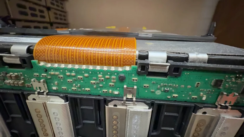
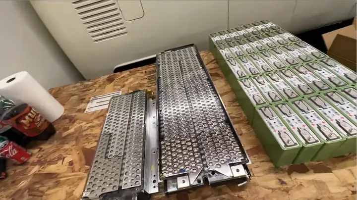
I started this Sprinter van electrical overhaul in my bay by completely dismantling a hazardous, thrown-together DC power installation. This 170 rear-wheel drive Sprinter rolled into the shop with sloppy cable routing, undersized copper wiring, and unsafe breakers that demanded an immediate teardown.
⚡ Quick Guide: How to Make It in 11 Steps
- Inspect the van and plan layout.
- Check amateur wiring and breakers.
- Trace undersized gauge runs.
- Examine Wfco box and bus bars.
- Identify bad DC/DC input breakers.
- Select new Victron and Lynx parts.
- Mount Lynx power center on board.
- Install 4/0 cables and Class T fuse.
- Wire solar panels through double breaker.
- Program Victron system for lithium.
- Test battery capacity and output.
📋 In This Article
- Technical Specifications & Components
- Tools & Materials Used — what you will need for this project
- Van Electrical Inspection and Assessment
- Inspecting Amateur Cable Management
- Tracing Undersized Cable Runs
- Identifying Wfco Box Wiring Faults
- Planning the Electrical Restoration
- Selecting New Victron Components
- Mounting the Lynx Power Center
- Installing 4/0 Cables and Class T Fuse
- Wiring Solar Breakers and MPPT
- Programming the Victron System
- Final System Testing and Capacity Check
- FAQ
📊 Technical Specifications & Components
| Base Vehicle | 170 Rear-Wheel Drive Sprinter |
| Battery Bank | 3 Battle Born LiFePO4 Batteries |
| Inverter/Charger | Victron MultiPlus |
| System Monitoring | Victron Cerbo GX |
| Solar Charge Controller | Victron MPPT |
| Main Battery Fuse | Class T Fuse |
| Main Cable Size | 4/0 AWG |
| DC/DC Input Protection | Oran XS Smart Shunt & Lynx Power In |
📊 Project Overview & Costs
🔧 Difficulty Level: Hard
⏱️ Time Investment: DIY: 16 to 24 hours | Pro: 8 to 10 hours
💰 Professional Service Cost: $1,500 - $2,500
💡 Verdict: Complete DIY execution eliminates labor expense for technicians experienced in DC distribution systems.
🛠️ Tools & Materials Used
Repair Walkthrough
Van Electrical Inspection and Assessment
The job began with a full walkaround of the 170 Sprinter to inspect what the previous builder abandoned behind the interior panels. The client brought this van to the shop for a complete overhaul of both the electrical network and the plumbing layout, which included removing an oversized shower stall to fit a fold-down pan. The primary power compartment was inspected and revealed a disorganized cluster of mismatched electrical gear. Bad work. It was immediately clear that essential circuit safety measures were treated as an afterthought during original construction. Almost every single wire and component inside the housing had to be stripped out.
Inspecting Amateur Cable Management
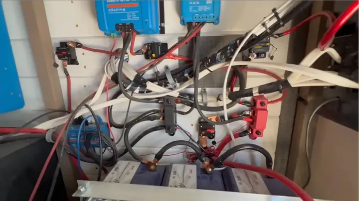
The panel was pulled off the battery bay to inspect the three Battle Born batteries and their connecting bus wires. The cable management showed poor workmanship throughout the power cabinet. The previous installer ran thin speaker wires next to high-current feeder lines, fastened massive copper lugs onto undersized terminal studs, and fitted improper breakers. A 250 amp breaker was found functioning as the primary battery disconnect, which exceeded reasonable ampacity limits for that specific wire length. High hazard. Loose, undersized terminations like those generate excessive thermal buildup and drop operating voltage under heavy load.
Tracing Undersized Cable Runs
Every cable across the mounting panel was traced to identify the exact wire gauge used in each branch circuit. A heavy conductor was found jammed into a screw terminal rated for 10 AWG maximum, forced inside by sheer physical leverage. Near the Victron MultiPlus unit, the inverter was connected with 1/0 AWG wire where the manufacturer explicitly specifies 4/0 AWG cable. A Victron Cerbo GX monitoring unit was located mounted directly beside the inverter board. The original electrical layout defied basic system logic. Pure junk.
Identifying Wfco Box Wiring Faults
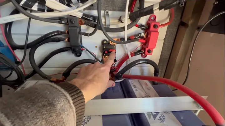
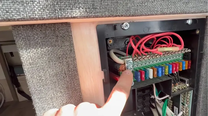
The cover plate was pulled off the Wfco distribution center to examine the internal 12V fuse panel connections. A thick battery feeder was jammed straight into an entry lug designed for 4 AWG wire, feeding a sub-panel rated for only 100 amps total continuous load. Multiple standalone bus bars were mounted randomly across the rear plywood panel, creating a cluttered space that blocked easy diagnostic work. Every single branch circuit was noticed pulled tight against the chassis wall without any service loop left for future troubleshooting. Rough setup.
Planning the Electrical Restoration
The circuit breaker feeding the DC/DC charger line was inspected. A 250 amp unit was found installed there, which offered zero real overcurrent protection for that smaller conductor branch. The access panel on the Victron MultiPlus inverter was removed to inspect the DC terminal blocks for arc damage or heat discoloration. The terminal screws had backed off and loosened, though the plastic housing showed no sign of scorching or melting. Clean terminals. Wire cutters were prepared to strip out all the legacy wiring and discarded components.

Selecting New Victron Components
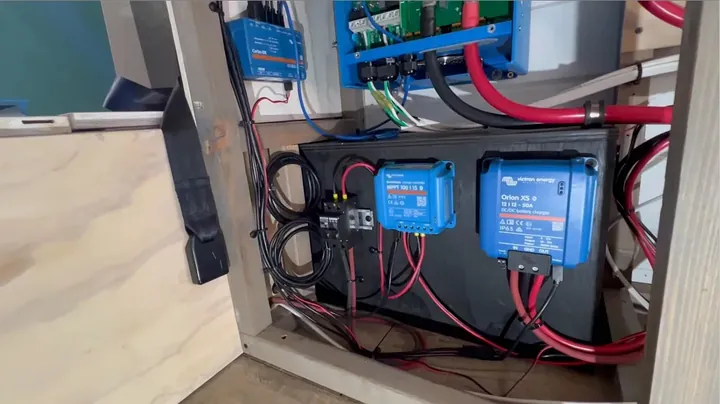
Every improper breaker was unbolted, the loose bus bars were removed, and all the unsafe power cables were stripped out from the enclosure. The Victron Cerbo GX and the MPPT solar charge controller were retained since both units tested within factory spec. An older DC converter was replaced because it lacked communication protocols for the GX Touch display and could not deliver higher charge rates. The replacement hardware was unpacked, including a modified Victron Lynx Power In unit, an Orion XS smart shunt, a heavy-duty Class T fuse block, and a high-amp battery disconnect switch.
Mounting the Lynx Power Center
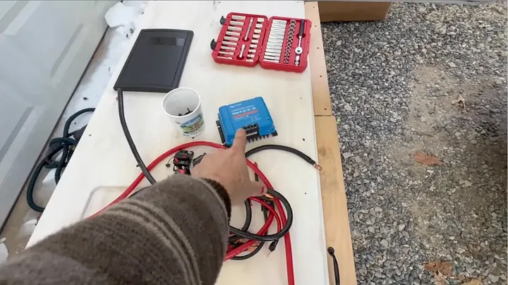
The Victron Lynx Power Center was fastened onto a custom wooden backer panel spaced away from the sheet metal van chassis. This standoff arrangement allowed the main chassis wire bundle coming through the wall to pass smoothly behind the board directly into the Wfco box without pinching. The factory crimp connectors were left untouched because disturbing that tight loom risked breaking delicate branch circuits. Clean 4 AWG cables were routed directly into the primary distribution box. Zero tension.
Installing 4/0 Cables and Class T Fuse
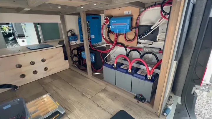
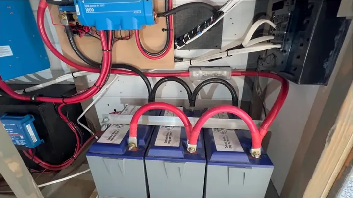
Heavy 4/0 fine-strand copper cables were routed to all three lithium batteries to eliminate voltage drop under high inverter loads. A Class T fuse was positioned directly at the positive battery terminal to guarantee rapid arc quenching during an extreme short circuit. A heavy-duty Blue Sea disconnect switch was installed inside the cabinet rather than mounting a basic marine switch on the outer panel face. Accessing the main electrical bay requires removing the protective panel regardless, so housing the battery disconnect switch inside keeps the terminal connections safe from accidental bumps.
Wiring Solar Breakers and MPPT
A double-pole DIN-rail breaker was clipped into place to isolate the solar array feed originating from the roof panels. 6 AWG solar wire was attached from the roof array into the line side of the breaker, stepped down to 10 AWG entering the MPPT charger, and 12 AWG was used on the output side since the controller caps at 15 amps. The Victron MultiPlus inverter was verified to initiate its active charge cycle as soon as shore power engaged. Every intelligent Victron component was hooked up to the Cerbo GX monitor using dedicated VE.Direct data cables.
Programming the Victron System
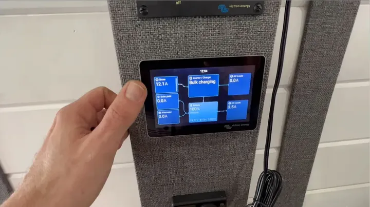
The Cerbo GX system was powered up, and the operating firmware was updated to the latest release version. The display screen immediately reflected real-time telemetry for shore power, solar harvesting, and alternator charging status on a single screen. Inspection revealed that the original installer left the inverter charger on factory lead-acid profiles without programming lithium battery parameters. The exact absorption and float voltage thresholds were programmed into the charger settings to top off the battery bank properly. The owner will gain significantly higher usable amp-hour capacity from this revised configuration.
Final System Testing and Capacity Check
Every VE.Direct communication link was checked, and the complete DC power network was stress-tested under load. The electrical installation performed cleanly across all charging sources. Every charge voltage parameter matched Battle Born factory specifications exactly down to the decimal point. Every screw and lug connection across the entire board was torque-checked to eliminate loose terminals. Job complete.
⚠️ CAUTION: SAFETY WARNING!
Safety warning: Disconnect main battery bank prior to removing bus bars or transferring primary DC conductors to eliminate severe electrical arcing hazards.
Summary & Tips
Rebuilding this Sprinter van electrical cabinet eliminated dangerous undersized wiring and improperly rated circuit breakers. Installing upgraded Victron components with structured cable management ensures reliable off-grid power generation for years to come. Clean work. The access panel was screwed shut, and the van was cleared for road testing.
📋 FAQ
❓ Why is a Class T fuse required for lithium battery banks?
Lithium battery chemistry exhibits extremely low internal resistance, capable of delivering thousands of amperes during short-circuit conditions. A Class T fuse provides an extremely high interrupt capacity (AIC) rating, stopping catastrophic fault currents before conductor insulation melts.
❓ What cable gauge is required for a Victron MultiPlus inverter?
Manufacturer specifications mandate 4/0 AWG copper conductor wire for 3000VA inverter configurations. Inadequate wire sizing causes excessive resistive heat generation and severe DC voltage drop under high surge loads.
❓ Why is a Victron Lynx Power In preferred over discrete bus bars?
Unenclosed standalone bus bars create exposed high-current junction points vulnerable to short circuits and debris accumulation. Modular distribution blocks consolidate high-amp connections into a safe, covered, insulated housing.
❓ Is programming required when connecting Victron inverters to Battle Born LiFePO4 batteries?
Factory default inverter settings reflect lead-acid charging curves, which apply incorrect absorption voltages and float stages to LiFePO4 cells. Custom programming prevents battery management system shutdown and premature cell degradation.
❓ Is mixing wire gauges permissible across solar MPPT controller circuits?
Wire gauge reductions are permissible provided conductors meet circuit amperage demands and overcurrent protection specs. High-voltage roof feeds require larger gauge cables to limit line loss over long distances, whereas controller output runs conform to rated output current.
Disclaimer: Tooling and materials utilized in this guide were acquired independently. Content includes affiliate tracking links; qualifying purchases generate a referral commission without increasing end-user cost.