Mounting a high-amp solar charger like the Victron 450/200 demands precise planning for protective conduits and safety switches. This unit manages substantial loads, incorporating four dedicated MPPT circuits alongside a 450-volt capacity. Getting the electrical connections right is critical when handling 200 amps of power. Let’s examine how to fit this hardware into the current layout.
⚡ Quick Guide: How to Make It in 10 Steps
- Identify the 450/200 controller inputs and battery terminals.
- Size all battery cabling for 200A current flow.
- Install a code-compliant PV disconnect switch box.
- Adapt conduit entries for secure cable management.
- Verify the unit model and connector compatibility.
- Plan conduit routing to avoid cable strain.
- Remove the cover using the angled screw access points.
- Disassemble the internal MC4 terminal blocks if needed.
- Drill custom conduit holes for clean wire entry.
- Finalize the installation and test connections.
📋 In This Article
- Technical Specifications & Components
- Tools & Materials Used — what you will need for this project
- Assessing the Victron 450/200 Controller
- Sizing Cables for 200A Loads
- Installing the PV System Disconnect
- Managing Conduit and Breaker Integration
- Understanding the MC4 Connector Update
- Adapting Conduit for MC4 Models
- Optimizing Cover Screw Access
- Removing the Terminal Cover
- Customizing Conduit Entry Points
- Finalizing the Installation Setup
- FAQ
📊 Technical Specifications & Components
| Max Charge Current | 200A |
| Max Input Voltage | 450V |
| MPPT Trackers | 4 independent inputs |
| Battery Connection | Positive and Negative terminals |
| Disconnect Requirements | Simultaneous positive and negative break |
| Connector Type | MC4 (on newer models) |
📊 Project Overview & Costs
🔧 Difficulty Level: Medium
⏱️ Time Investment: DIY: 3-4 hours | Pro: 1-2 hours
💰 Professional Service Cost: $200-$400
💡 Verdict: Self-installation eliminates contractor labor overhead.
🛠️ Tools & Materials Used
• Conduit fittings
• 250A circuit breaker
• 8-position PV disconnect switch
Victron 450/200 MPPT - Step-by-Step Guide
Assessing the Victron 450/200 Controller
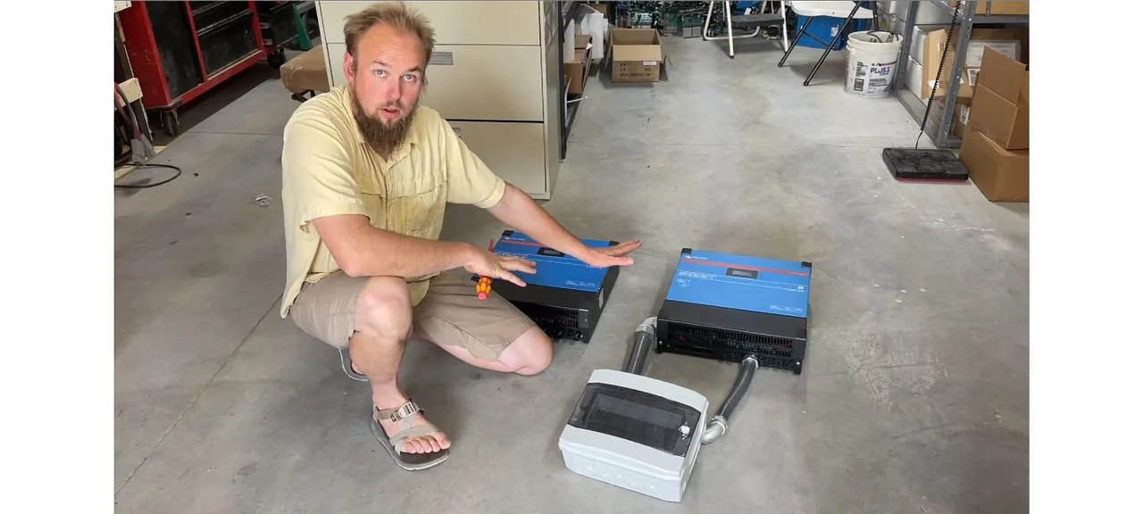
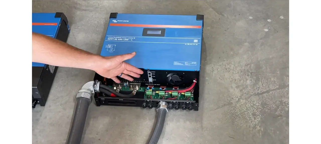
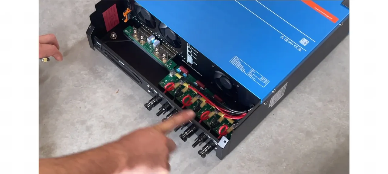
I examined the hardware first. This Victron model handles 200 amps and accepts 450 volts on the input side. Four separate MPPT circuits sit inside the casing. Removing the front panel exposes the interior layout. Space is limited. The negative and positive battery terminals are mounted right up front. It's built heavy.
Sizing Cables for 200A Loads
Every conductor here must be rated for 200 amps. I used heavy gauge copper. Locating a heavy-duty breaker or switch for the battery circuit takes effort. Safety disconnects must absorb transient surges. Undersized components present fire hazards. Proper sizing is mandatory.
Installing the PV System Disconnect
This enclosure provides necessary circuit isolation. I deployed an 8-position switch to control all four MPPT inputs simultaneously. The mechanism breaks both positive and negative lines together. Electrical code mandates this configuration. Controlling DC arcs requires strict adherence to safety standards.
Managing Conduit and Breaker Integration
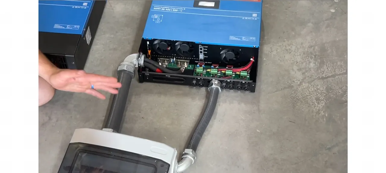
I routed the conduit straight into the housing. Removing standard cable glands allowed me to drill custom entry holes. This creates a clean finish. I paired this with a 250-amp breaker on the output. Fused circuits permit higher ratings up to 500 amps. The assembly meets all electrical specifications. The final build remains entirely secure.
Understanding the MC4 Connector Update
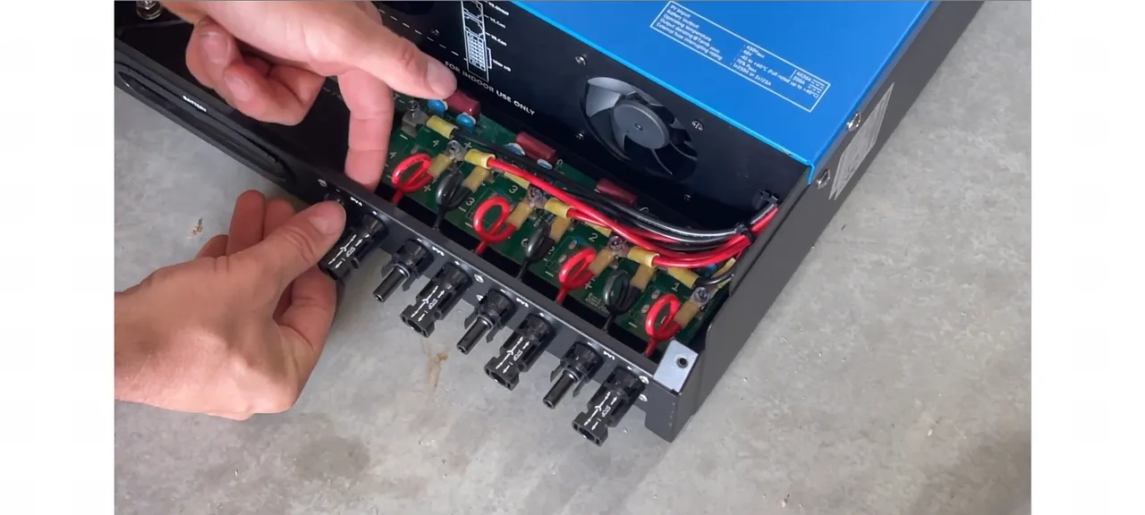
Manufacturer updates shifted production toward MC4 interfaces. European markets favor this layout over traditional American conduit wiring methods. Exposed wire runs present routing challenges. Installers must adapt traditional protective tubing to these plug-in terminals.
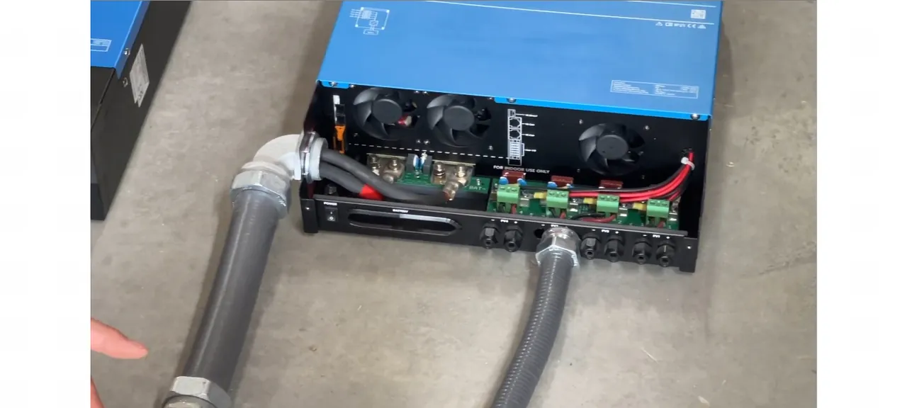
Adapting Conduit for MC4 Models
Conduit integration remains feasible on revised hardware iterations. Drilling alternative clearance holes solves layout conflicts. MC4 ports require minor adjustments. Standard protective enclosures fit this revision.
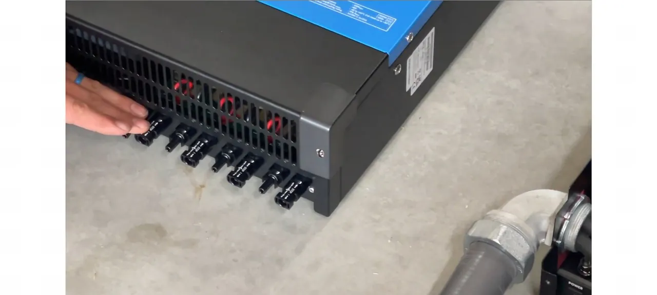
Optimizing Cover Screw Access
Fastener orientation changed on the housing cover. Older iterations utilized vertical screw shafts requiring deep tool clearance. Angled fastener receivers reduce spatial constraints. Shorter conduit drops suffice. This design improves accessibility.
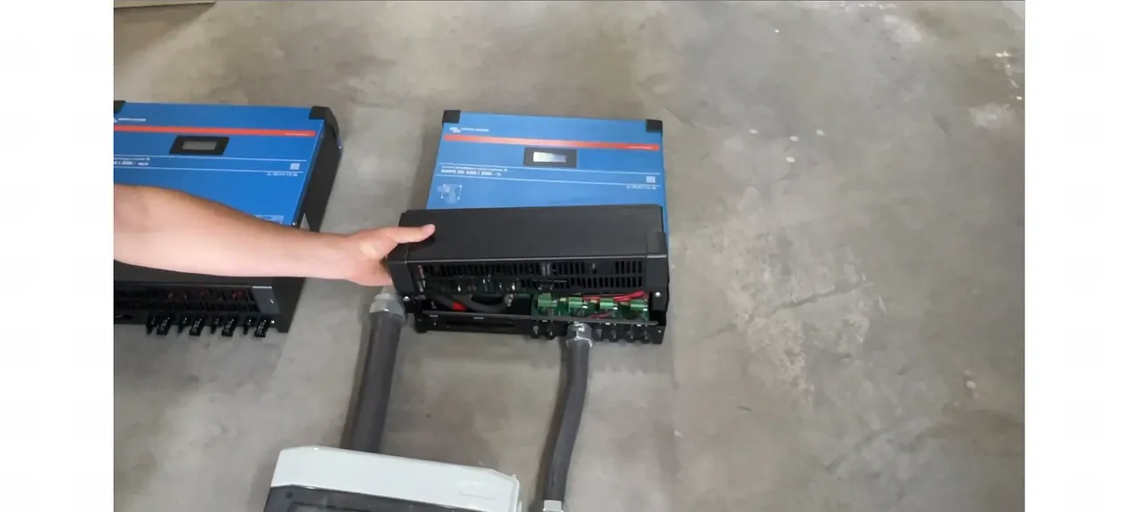
Removing the Terminal Cover
Extracting two retainer screws releases the protective cover. Internal MC4 lines connect directly to the busbars. These terminal assemblies disengage via rear mounting nuts. Component removal is straightforward.
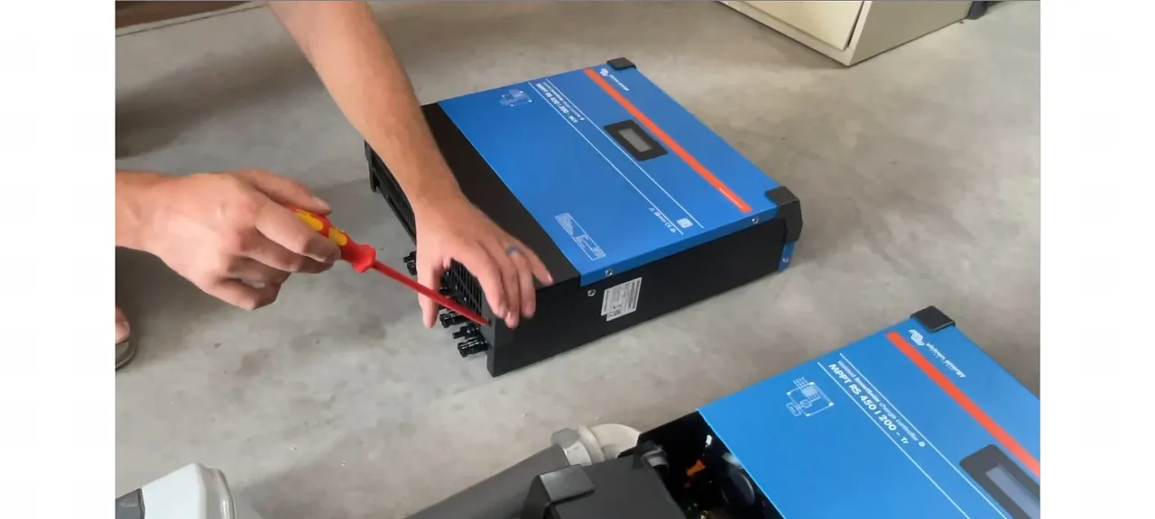
Customizing Conduit Entry Points
Clearing the factory terminals allows drilling custom conduit ports. Dual smaller runs integrate cleanly into wire gutters. Single larger conduits serve distribution panels effectively. Layout configuration remains flexible.
Finalizing the Installation Setup
This procedure completes the hardware mounting sequence. Technical inquiries receive prompt assistance in comments. The controller operates reliably. Assembly is complete.
⚠️ CAUTION: SAFETY WARNING!
Disconnect all photovoltaic and battery supplies prior to servicing internal electronics. DC arcs present severe burn hazards and equipment failure risks.
Summary & Tips
Mounting this Victron controller proceeds efficiently with early conduit planning. Angled fastener alignments resolve space limitations in compact mechanical rooms. Cable gauges must match specified current capacities. The completed assembly provides reliable power regulation.
📋 FAQ
❓ Can I use conduit with the new MC4 model?
Factory glands detach to permit custom casing modifications. Direct drilling maintains code compliance and clean runs.
❓ Why are the screws angled on the new model?
Angled fasteners reduce vertical clearance requirements, eliminating the need for extended conduit drops.
❓ Do I really need a 200A disconnect?
High-amperage circuits require rated load-break switches to maintain operating safety standards.
❓ Are the terminals easy to work with?
Busbar assemblies feature threaded retention nuts supporting modular disassembly and entry redesign.
Disclaimer: Equipment acquired independently. Post includes affiliate links generating commissions without added buyer expense.