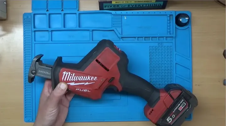
Picked up this Milwaukee M18 Hackzall on Facebook Marketplace for twenty quid. It emitted a faint relay click and a brief LED flash, but the blade didn’t move. Fixing cordless brushless tools requires cutting through rubberized potting resin, inspecting surface-mount power MOSFETs with a microscope, and tracing high-voltage gate failures.
⚡ Quick Guide: 15-Step Repair Process
- Unscrew the housing with a Torx T10.
- Pull the motor and speed control module.
- Separate the brushless motor assembly.
- Examine Hall effect sensors for damage.
- Remove silicone potting using isopropyl alcohol.
- Analyze repair costs versus unit replacement.
- Desolder the header pins between boards.
- Remove heatsink to access MOSFETs.
- Inspect transistors under a digital microscope.
- Use hot air to desolder the faulty MOSFET.
- Test gate-to-source pins with a multimeter.
- Verify phase transistors for stress.
- Install new MOSFETs and join PCBs.
- Align battery terminals and test trigger.
- Perform thermal scan for MCU failures.
📋 In This Article
- Technical Specifications & Components
- Tools & Materials Used — items required for this build
- Initial Inspection & Clamshell Disassembly
- Extracting Internal Electronics & Motor Assembly
- Disassembling the Brushless Motor Mechanism
- Checking Hall Effect Sensors & Mechanical Clearance
- Digging Out Potted Circuit Boards
- Evaluating Replacement Cost vs Repair Feasibility
- Desoldering Sandwiched Control Boards
- Uncovering the MOSFET Driver Array
- Microscopic Inspection of Power MOSFETs
- Hot Air Rework & Desoldering Damaged Transistors
- Multimeter Diode & Resistance Testing
- In-Circuit Testing & Selecting Replacement MOSFETs
- Surface-Mount Soldering & PCB Sandwich Reassembly
- Rehousing Internal Components & Dry Run
- Thermal Diagnosis of Catastrophic MCU Failure
- FAQ
📊 Technical Specifications & Components
| Tool Model | Milwaukee M18 Hackzall Reciprocating Saw |
| Operating Voltage | 18V DC |
| Motor Architecture | 3-Phase Brushless DC (BLDC) |
| Main Controller Chip | DRV91670 (Integrated MCU + Pre-Driver) |
| Power Inverter Configuration | 6x Surface-Mount N-Channel MOSFETs |
| Potting Material | Soft Rubberized Silicone Compound |
| Housing Fasteners | Torx T10 Shell Screws |
| Rotor Sensing | 3x Hall Effect Position Sensors |
📊 Project Overview & Costs
🔧 Difficulty Level: Hard
⏱️ Time Investment: DIY: 4 - 6 Hours | Pro: 2 Hours
💰 Professional Service Cost: $150 - $220
💡 Verdict: Component-level repair offers savings versus full motor assembly replacement, provided high-voltage spikes haven't destroyed the controller IC.
🛠️ Tools & Materials Used
• Dental Pick
• Isopropyl Alcohol (99%)
• Desoldering Vacuum
• Desoldering Wick & Flux
• Replacement MOSFETs
• Thermal Camera
Testing and Results
Initial Inspection & Clamshell Disassembly
I started by testing the tool with a full 18V battery. The LED activated and the trigger generated an internal click, but the motor didn't spin. I verified the blade shaft manually to ensure the transmission wasn't seized. It rotated freely. Mechanical failure was ruled out.
Extracting Internal Electronics & Motor Assembly
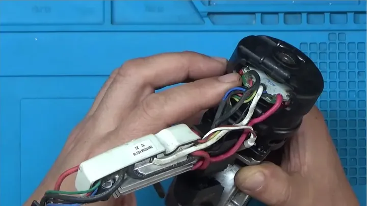
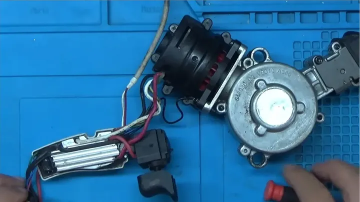
I removed the drivetrain and control module from the housing. Milwaukee pots these modules in black plastic to dampen vibration and prevent moisture damage. The rear PCB connects to the stator and a ribbon cable carrying Hall effect sensor signals. The MOSFETs were tucked away.
Disassembling the Brushless Motor Mechanism
I separated the motor from the metal gearbox to reach the sensor PCB. A larger Torx bit loosened the motor bolts. Once open, I checked the rotor shaft and front bearing. The bearing showed slight wear, but it wasn't enough to stop the motor from turning.
Checking Hall Effect Sensors & Mechanical Clearance
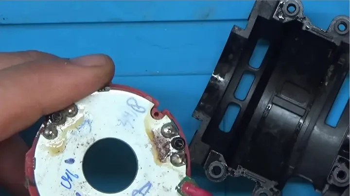
I cleaned the dust from the stator and inspected the sensors. Misaligned rotors often strike these sensors. The three sensors appeared intact with no visible damage. Just a lot of debris.
Digging Out Potted Circuit Boards
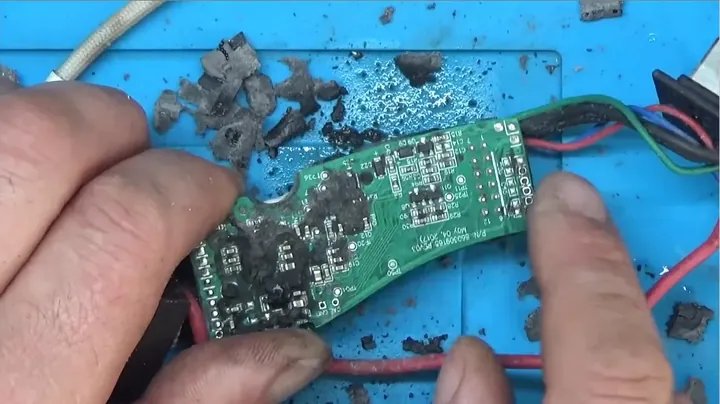
I pried the module from its housing. I used a dental pick and 99% isopropyl alcohol to remove the silicone. It's slow work. The solvent helps the silicone peel away. I realized the controller is actually a dual-board assembly held together by potting.
Evaluating Replacement Cost vs Repair Feasibility
Milwaukee doesn't offer individual boards. You have to buy the entire potted assembly, which costs nearly as much as a new tool. Component repair is the only logical path.
Desoldering Sandwiched Control Boards
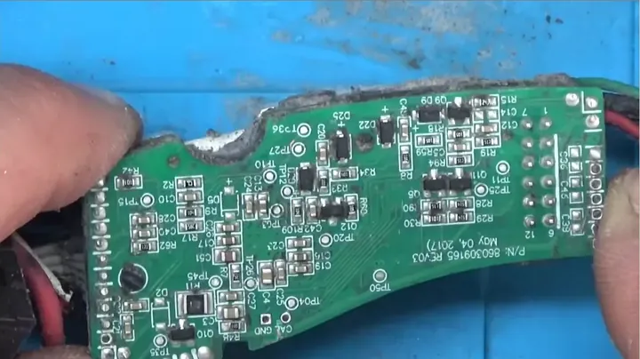
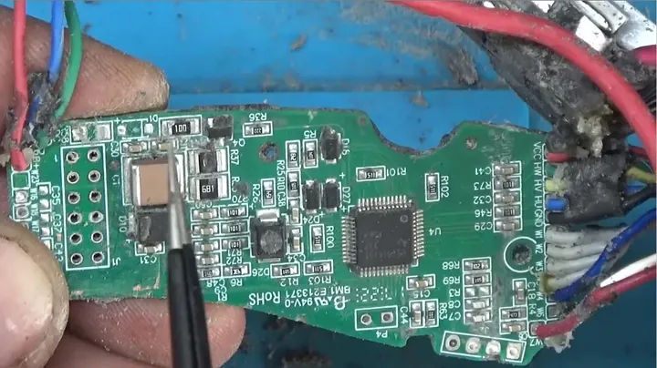
I used a vacuum desoldering tool at 380°C to clear the interconnect pins. Once clear, I separated the boards. The lower board contains the DRV91670 controller, which combines the MCU and pre-driver in one chip.
Uncovering the MOSFET Driver Array
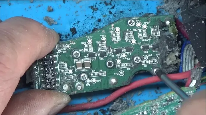
I removed the heatsink screws. The board uses six surface-mount MOSFETs for the H-bridge. Lifting the heatsink showed carbon residue around one of the transistors.
Microscopic Inspection of Power MOSFETs
Under the microscope, I saw the MOSFET had failed completely. The epoxy package was split with clear cratering near the gate trace. These failures often occur when high current shorts through the gate.
Hot Air Rework & Desoldering Damaged Transistors
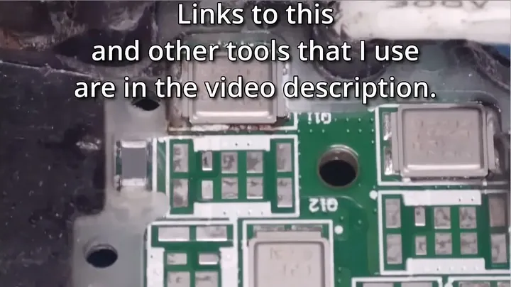
I removed the rubber seal to prevent melting. I used flux and 360°C hot air to heat the substrate. Once the solder flowed, I lifted the transistor with tweezers. I used copper braid to clean the residual solder.
Multimeter Diode & Resistance Testing
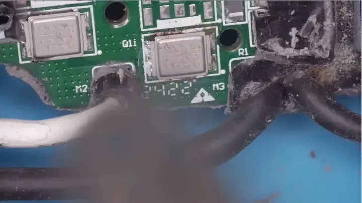
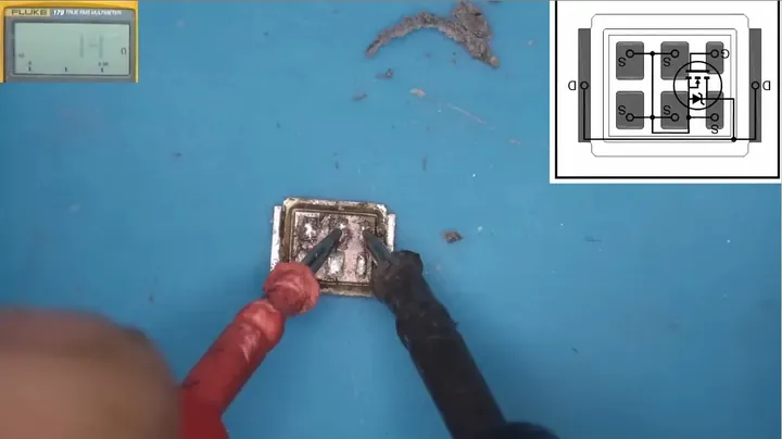
I tested the MOSFET. It showed a permanent 8-ohm resistance instead of proper gate isolation. The transistor was dead.
In-Circuit Testing & Selecting Replacement MOSFETs
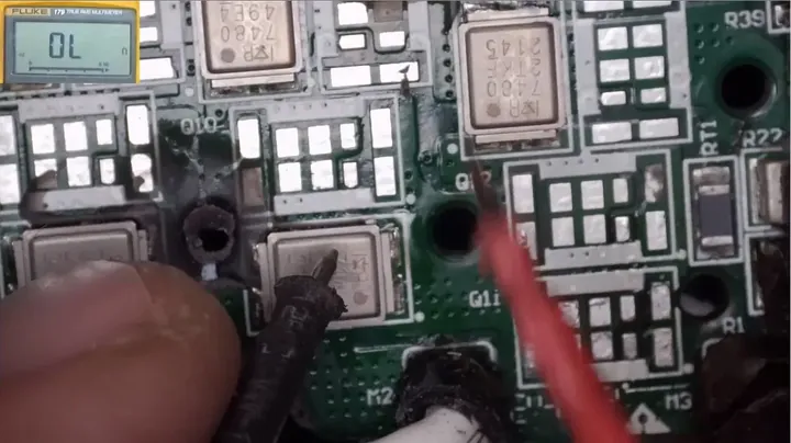
I tested the remaining transistors to ensure they were safe. High-current failures often stress adjacent components. I opted to replace both MOSFETs on that phase leg to be safe.
Surface-Mount Soldering & PCB Sandwich Reassembly
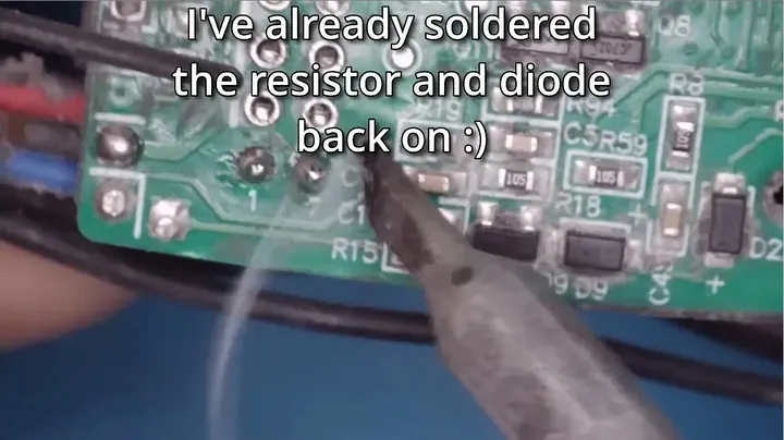
I preheated the board, tinned the pads, and placed the new MOSFETs. I reflowed the solder with hot air. I reattached the heatsink, joined the two boards, and soldered the header pins.
Rehousing Internal Components & Dry Run
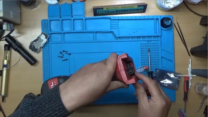
I organized the internal wiring and battery terminals back into the frame. I closed the shell and inserted the battery. The trigger activated the LED, but the motor remained dead.
Thermal Diagnosis of Catastrophic MCU Failure
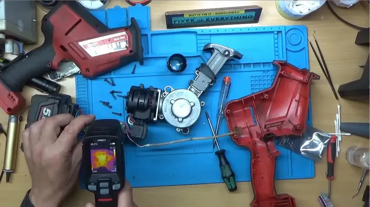
I opened it up and used a thermal camera on the logic board. The controller IC was overheating. When the MOSFET failed, it dumped 18V into the microcontroller, destroying the internal logic. Without access to the proprietary firmware, the unit is non-repairable.
⚠️ CAUTION: SAFETY WARNING!
Remove all batteries before opening tools. Shorting lithium-ion terminals or capacitors can cause fires or molten solder splatter.
Summary & Tips
MOSFET replacement is feasible with basic rework tools. However, a gate-shorted MOSFET often destroys the MCU, and without factory firmware, that board is scrap.
📋 FAQ
❓ Can you test MOSFETs without desoldering them?
No. Parallel inverter configurations create shared paths, which hide component failures. You must remove them to verify.
❓ Why is potting compound used in power tools?
It protects internal circuitry from moisture, dust, and vibration. It makes repairs difficult but improves longevity.
❓ Where can I buy replacement motor controller chips?
Buying bare chips is ineffective. Milwaukee's custom firmware is factory-flashed and not available to the public.
❓ Is it worth to buy broken tools online?
It depends on the damage. Mechanical issues are easy to fix, but burned electronics usually aren't worth the cost of replacement parts.
Disclaimer: I bought these tools myself. This post contains affiliate links; I may earn a commission if you make a purchase.