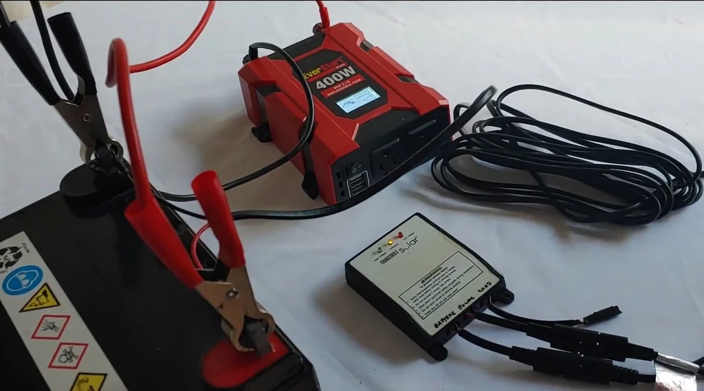
Swapping a modified sine wave inverter for a pure sine model sounds like an obvious win for any 12V solar setup. But does the cleaner waveform justify the higher idle power draw? By testing a standard AC fan, LED bulbs, and a phone charger, we can measure exactly how different loads respond to these two power delivery methods and whether the efficiency trade-off is worth the upgrade.
⚡ Quick Guide: How to Make It in 5-10 Steps
- Perform baseline idle and load testing on the modified sine inverter.
- Isolate the DC power source and disconnect the old inverter.
- Measure and mark mounting holes for the new, physically larger unit.
- Drill the mounting surface and clear all conductive debris.
- Install the pure sine inverter and verify all DC connections.
- Conduct a fresh round of idle and load tests to compare performance.
📋 In This Article
- Technical Specifications & Components
- Tools & Materials Used — what you will need for this project
- Planning the 12V Solar Upgrade
- Measuring Modified Sine Idle Draw
- Testing Fan Performance Under Modified Sine
- Observing LED Flicker and Charger Noise
- System Isolation and Shutdown
- Comparing Inverter Specifications
- Removing and Installing the Inverter
- First Startup with Pure Sine
- Analyzing Idle Power Consumption
- Fan Test with Pure Sine Wave
- Visual Improvement in LED Lighting
- Charger Behavior and Final Measurements
- Why Loads Behave Differently
- Final Verdict on the Upgrade
- Next Steps for the Solar Board
- FAQ
📊 Technical Specifications & Components
| Modified Sine Idle Current | 0.21 A |
| Modified Sine Idle Power | 2.6 W |
| Pure Sine Idle Current | 0.97 A |
| Pure Sine Idle Power | 12 W |
| Modified Sine Output Voltage | 223.5 V |
| Pure Sine Output Voltage | 221.1 V |
| Old Inverter Rating | 300 W |
| New Inverter Rating | 400 W |
| Fan Current (Modified) | 2.63 A |
| Fan Current (Pure) | 3.16 A |
| LED Current (Modified) | 1.2 A |
| LED Current (Pure) | 1.8 A |
📊 Project Overview & Costs
🔧 Difficulty Level: Medium
⏱️ Time Investment: DIY: 1.5 hours | Pro: 45 minutes
💰 Professional Service Cost: $80 - $150
💡 Verdict: The upgrade improves component longevity but increases daily standby energy consumption.
🛠️ Tools & Materials Used
• Clamp Meter
• Screwdriver Set
Step-by-Step Assembly, Repair, Testing & Inspection
Planning the 12V Solar Upgrade
This project focuses on the AC side of a small 12V solar board. Upgrading from a basic PWM controller to an MPPT unit was the first step in this system's evolution. Now, the goal is to replace a modified sine wave inverter with a pure sine wave unit. It's a significant change. We need to document how different loads react to the waveform shift. The goal is clarity.
Measuring Modified Sine Idle Draw
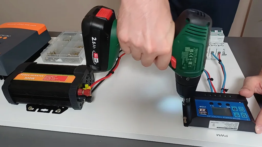
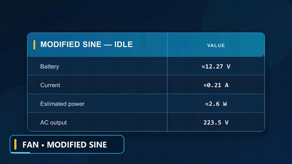
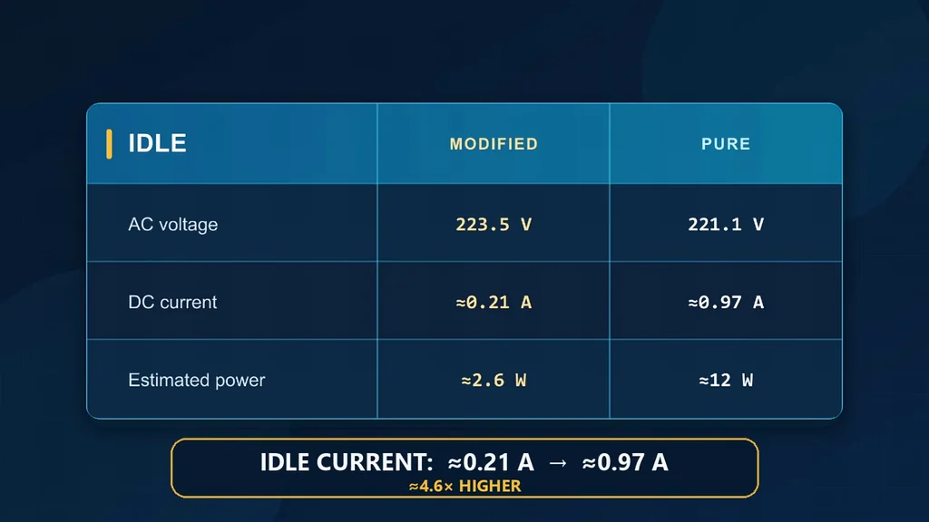
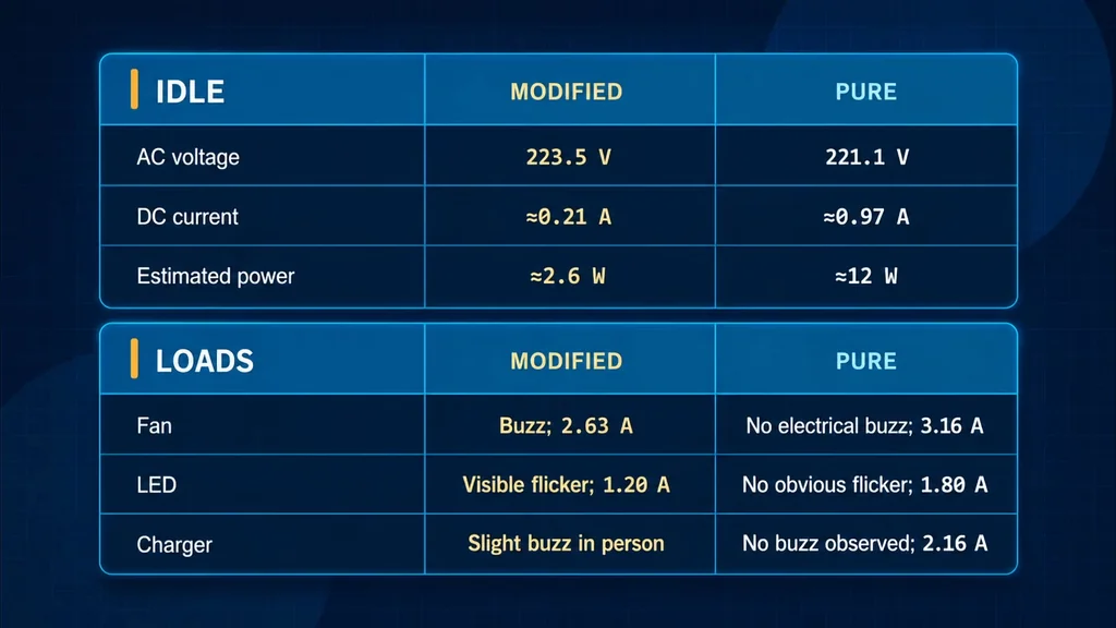
First, we establish a baseline with the old inverter at idle. With no AC load connected, the unit draws 0.21 amps from the 12V side. The battery voltage sits at 12.27V, resulting in roughly 2.6 watts of input power. The AC output measures 223.5 volts, which looks perfectly fine on paper. It's stable. The real test is how sensitive electronics handle the step waveform.
Testing Fan Performance Under Modified Sine
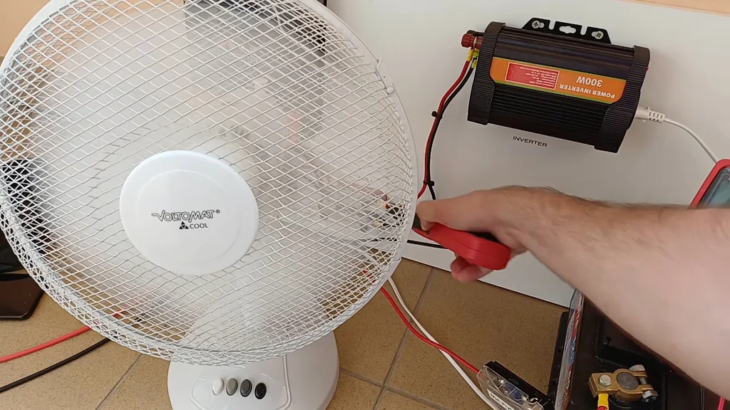
The first load is a standard AC fan. It spins up to normal speed without issue. However, the motor produces a distinct, harsh electrical buzz that shouldn't be there. It's loud. Total DC input current stabilizes at 2.63 amps while running. This noise is a clear indicator of the motor struggling with the non-sinusoidal waveform. We'll use this exact fan for the comparison test later.
Observing LED Flicker and Charger Noise
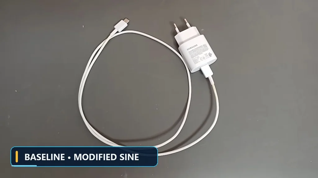
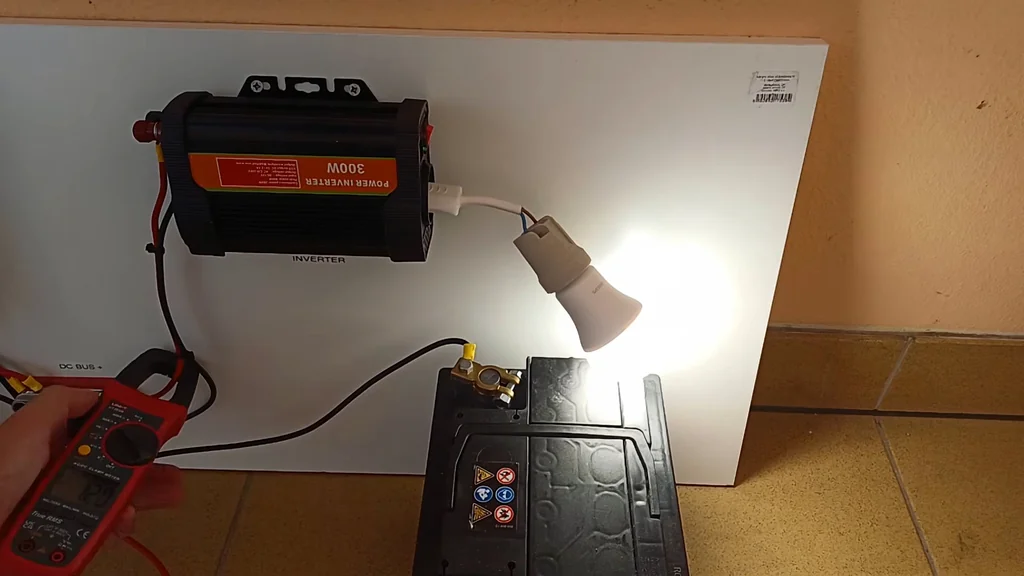
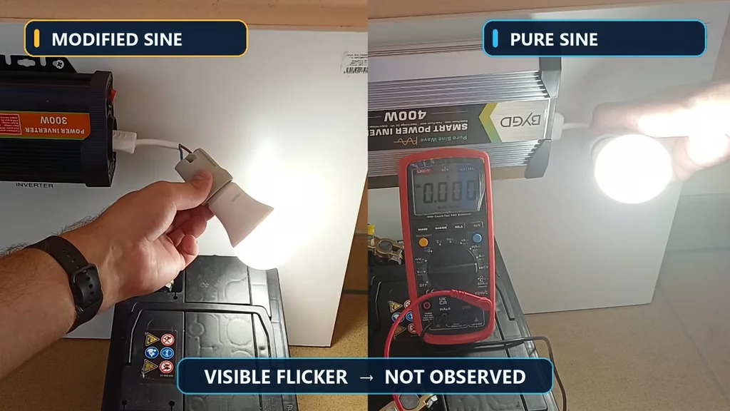
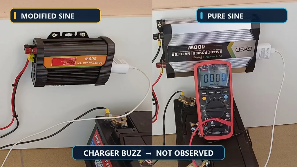
Next, we connect an LED bulb. It lights up, but the camera captures a clear, visible flicker. It's annoying. This happens because the LED driver is reacting to the sharp voltage transitions of the modified sine wave. The total input current is 1.2 amps. Additionally, a phone charger produces a slight audible buzz when you stand near it. The microphone doesn't pick it up well, but it's physically present. These issues are exactly what we hope to solve.
System Isolation and Shutdown
After the baseline tests, we disconnect the AC load. We then switch off the inverter and the DC breakers. It's dead. However, the meters still show 2.42 volts, proving that you should never trust a switch position alone. Always verify with a meter. Safety is paramount here. The old 300-watt inverter is now ready for removal.
Comparing Inverter Specifications
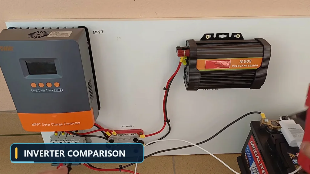
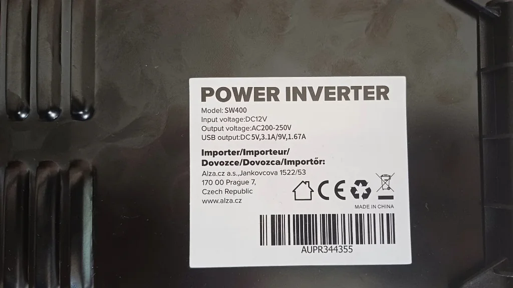
The replacement is a 400-watt pure sine wave unit. It's physically larger than the old 300-watt model. Its waveform is much closer to grid power, which is better for motors and transformers. That's the theory. But the label doesn't tell us about idle loss or real-world efficiency. We need to measure it ourselves. Data matters more than marketing.
Removing and Installing the Inverter
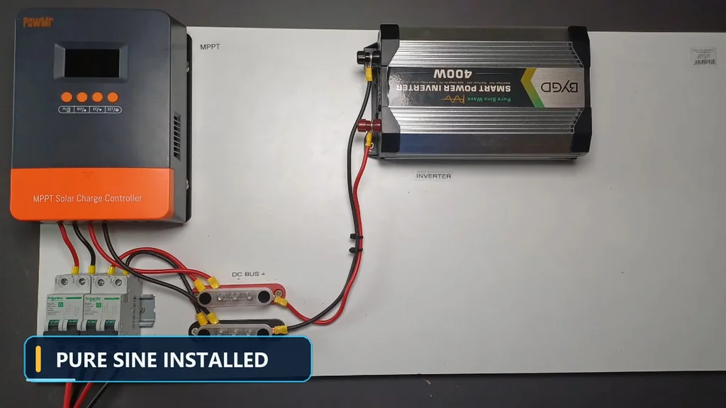
With the battery side isolated, we remove the DC leads and mounting screws. The new inverter is longer, so the old mounting points are useless. We mark the new holes and drill the board. It's messy. Before installing the electronics, we clear all drilling debris to prevent shorts. Conductive material is a risk. Finally, we secure the new inverter and route the DC cables.
First Startup with Pure Sine
The board is now complete. The MPPT controller, breakers, and bus bars remain in their original positions. Only the inverter has changed. We start with no load connected to the AC outlet. We switch on the DC side, then the inverter. It fires up normally. Everything is ready for testing. We need to check the idle power first.
Analyzing Idle Power Consumption
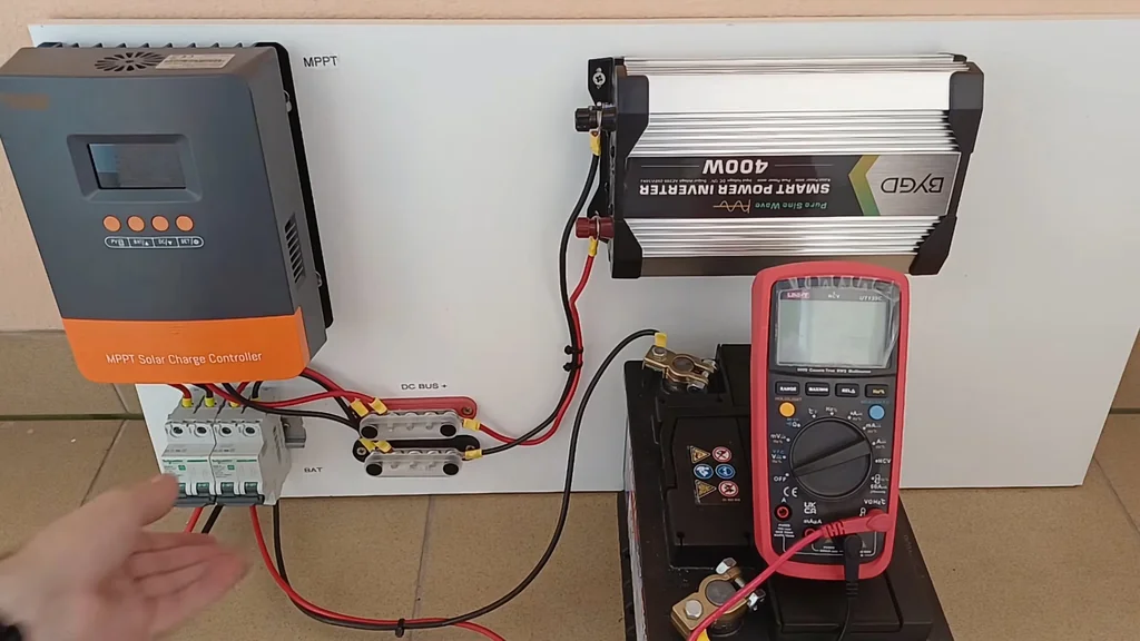
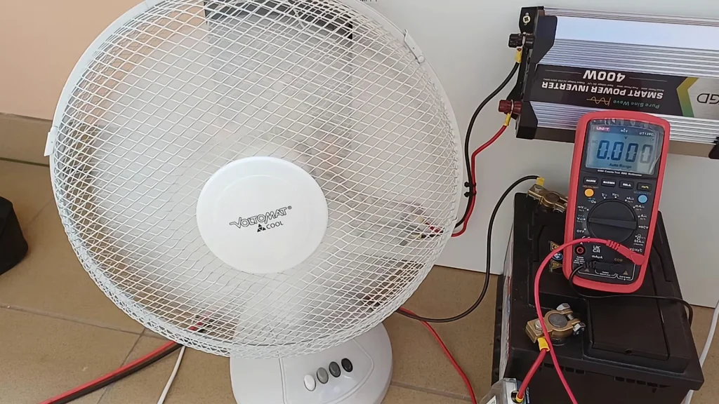
The AC output measures 221.1 volts, very close to the previous 223.5 volts. The battery voltage is 12.4V. Here is the surprise: the idle current is 0.97 amps, fluctuating around 1 amp. That's roughly 12 watts of input power. It's high. That's 4.6 times the idle draw of the old unit. Leaving this on all day carries a real energy penalty.
Fan Test with Pure Sine Wave
The fan starts normally, but the electrical buzz is gone. It's quiet. We only hear the mechanical sound of moving air. The difference is easy to hear. Battery voltage is 12.23V, and total input current is 3.16 amps. This is higher than the 2.63 amps we saw earlier. Part of that is the higher idle draw. It's expected.
Visual Improvement in LED Lighting
The LED test shows the clearest visual improvement. The bulb no longer shows the obvious flicker we saw before. It's smooth. I didn't use a laboratory flicker sensor, but the improvement is obvious to the naked eye. The total input current is 1.8 amps, compared to 1.2 amps before. The quality of light is much better.
Charger Behavior and Final Measurements
The phone charger no longer produces that slight buzz. It's silent. The pure sine test measured 12.27 volts and 2.16 amps of total input current. We didn't record a comparable current for the charger on the old inverter. It's a solid improvement. The electronics are clearly happier with the cleaner waveform.
Why Loads Behave Differently
Modified sine waves don't follow a smooth curve; they switch voltage in large steps. A multimeter shows a normal RMS voltage, but motors and transformers react to the sharp transitions with vibration and heat. It's harsh. A pure sine inverter creates a smoother waveform that mimics utility power. That's why the loads behave better.
Final Verdict on the Upgrade
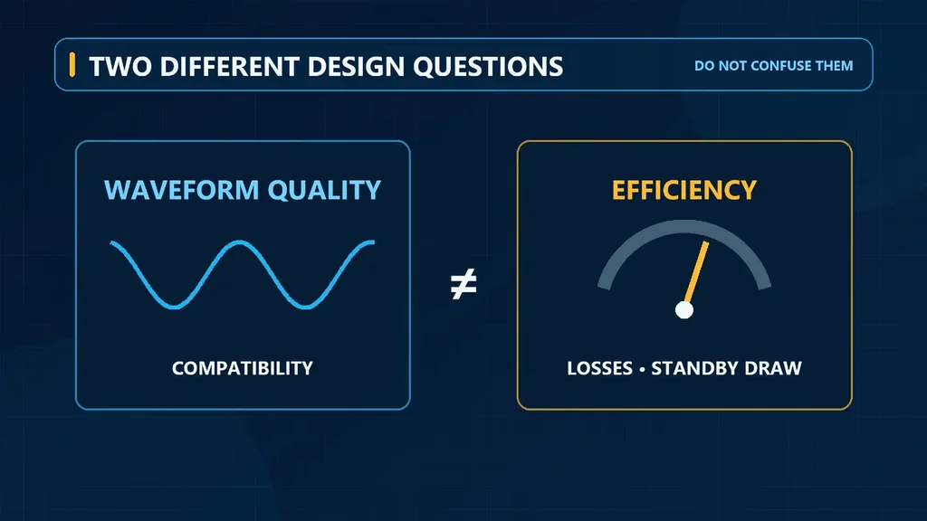
The upgrade clearly improved device compatibility. No fan buzz, no LED flicker, and no charger noise. It's clean. The trade-off is the idle consumption: 12 watts versus 2.6 watts. If you leave it on 24 hours a day, that's a lot of energy. You have to decide if the compatibility is worth the cost. It's a trade-off.
Next Steps for the Solar Board
The inverter is now pure sine, but those exposed breakers are still a problem. They need to go. In the next episode, the whole board gets a rebuild. It's necessary. We'll clean up the wiring and improve the safety of the entire system. Stay tuned for that.
⚠️ CAUTION: SAFETY WARNING!
Always verify polarity and use correctly rated fuses when working with 12V solar systems. Never assume a switch position equals zero voltage; always verify with a multimeter.
Summary & Tips
The pure sine inverter successfully eliminated electrical noise and flicker in our test loads. However, the significantly higher idle power consumption is a major factor for small solar systems. You must weigh the benefits of cleaner power against the continuous energy drain. This upgrade is a clear win for compatibility, provided your battery bank can handle the extra load.
📋 FAQ
❓ Is a pure sine inverter always better?
Usually, yes, for sensitive electronics. It prevents flicker and motor buzz. But, it often draws more idle power than modified sine units. You have to choose.
❓ Why did my fan buzz on the old inverter?
Modified sine waves are not smooth. They use sharp, stepped transitions. Motors struggle with this and vibrate. It creates that audible buzz.
❓ Does idle power draw really matter?
Honestly, it depends on your battery size. If you leave the inverter on 24/7, 12 watts adds up quickly. It can drain a small battery overnight.
❓ Should I upgrade my solar system?
Depends on your loads. If you only power simple tools, the old one is fine. If you run chargers or fans, the upgrade is worth it.
Disclaimer: I purchased all tools for this guide with my own money to ensure an unbiased review. This post contains affiliate links, meaning I earn a small commission if you make a purchase at no extra cost to you.