Three EG4 6000XP inverters mounted on my wall represent the core of my new off-grid homestead power system. I designed this setup to handle my energy needs on a budget, and I’m walking through the wiring and configuration process I followed. Before starting, I checked the latest manual online, as manufacturer updates can change specific installation requirements for these units.
⚡ Quick Guide: How to Make It in 15 Steps
- Mount all three EG4 6000XP units securely to the wall surface.
- Install 1-inch ENT connectors to manage cable entry points.
- Strip cable shielding carefully to avoid damaging internal conductors.
- Apply ferrules to all finely stranded wires for secure connections.
- Torque all terminal connections to exactly 18 inch-pounds or 2 Newton meters.
- Set dip switches for parallel operation: 2 up, 2 down, 2 up.
- Daisy-chain communication cables from right to left across all units.
- Commission the system according to the updated product manual procedures.
📋 In This Article
- Technical Specifications & Components
- Tools & Materials Used — what you will need for this project
- Mounting the 6000XP Inverters
- Installing ENT Connectors
- Preparing Wires with Ferrules
- Cutting and Stripping Cable Shielding
- Securing Terminal Connections
- Verifying Torque and Phase Wiring
- Removing Redundant Battery Splices
- Connecting Battery Cables
- Routing Negative Battery Cables
- Comparing Wire Flexibility
- Configuring Parallel Dip Switches
- Connecting Communication Cables
- Installing PV Isolators
- Finalizing System Commissioning
- Reviewing System Performance
- FAQ
📊 Technical Specifications & Components
| Inverter Model | EG4 6000XP Off-Grid |
| Terminal Torque | 18 inch-pounds (2 Nm) |
| Battery Terminal Torque | 4-5 Newton meters (approx. 40 inch-pounds) |
| Communication Protocol | Parallel daisy-chain |
| Dip Switch Configuration | 2 Up, 2 Down, 2 Up |
| Conduit Type | 1-inch ENT |
| Battery Type | EG4-LifePower4 48V 100Ah |
📊 Project Overview & Costs
🔧 Difficulty Level: Medium
⏱️ Time Investment: DIY: 6-8 hours | Pro: 3-4 hours
💰 Professional Service Cost: $800-$1,200
💡 Verdict: DIY installation saves significantly on labor costs while providing full control over the system configuration.
🛠️ Tools & Materials Used
• Torque Screwdriver Set
• Ferrule Crimping Tool Kit
• 10mm Socket Wrench
• Allen Key Set
• 1-inch ENT Connectors
Step-by-Step Assembly, Repair, Testing & Inspection
Mounting the 6000XP Inverters
I started by hanging all three 6000XP inverters on my wall. With the units in place, I focused on the wiring layout required to bring the system online. I must emphasize that I am not a professional, and these steps reflect my personal approach; always consult your local ordinances and the latest manual from the manufacturer's website before starting your own installation.
Installing ENT Connectors
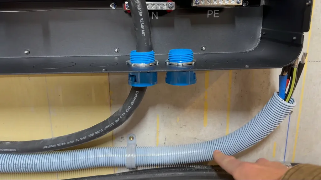
I added 1-inch ENT connectors to the inverters to secure my cable runs. These connectors snap into the housing, providing a clean entry point for the wiring. I double-checked the manual to ensure these were the correct fittings for my specific enclosure layout.
Preparing Wires with Ferrules
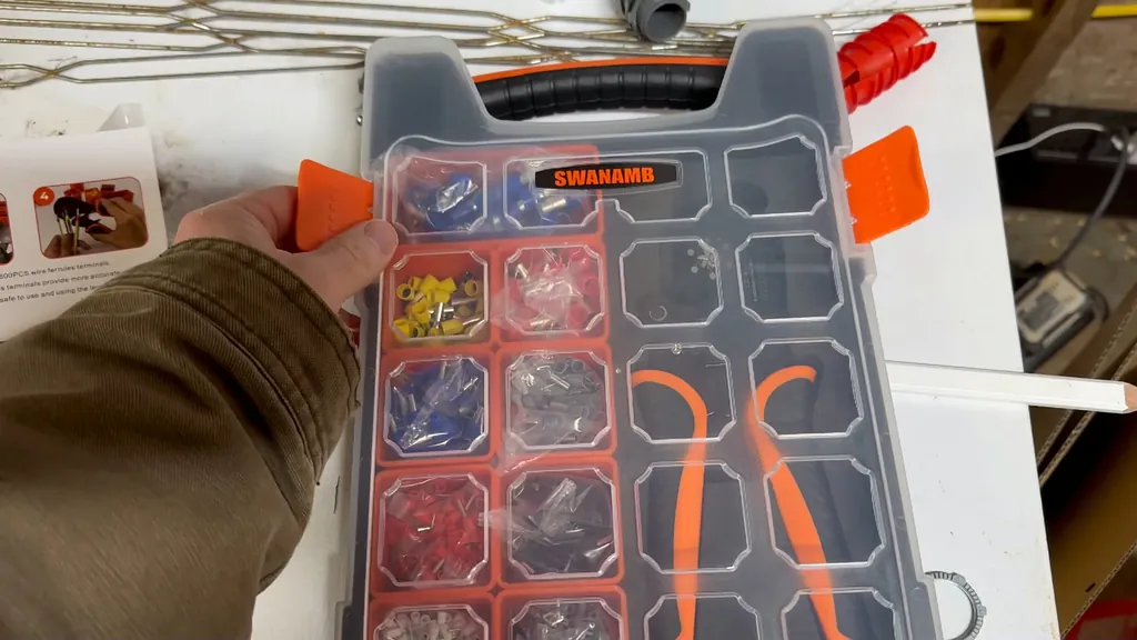
The manual specifically calls for ferrules when using finely stranded wires, so I picked up a dedicated crimping kit. I wanted a comprehensive set to handle various wire gauges without running out of parts mid-project. Using ferrules ensures the strands stay together under the terminal screw, which prevents loose connections and potential heat buildup.
Cutting and Stripping Cable Shielding
To strip the shielding without nicking the copper, I bent the cable sharply to expose the casing seam. I then made slow, shallow cuts along that bend, which allowed the shielding to peel away cleanly. This technique keeps the internal conductors pristine, which is vital when I'm working with expensive cabling. I made sure to leave enough length on the neutral and ground wires so I could easily route them to their respective terminals on the left and right sides of the block.
Securing Terminal Connections
I applied a small amount of heat to the plastic housing to make it more pliable, which helped me seat the cables into the terminals. Once the wires were positioned, I used my torque screwdriver to hit the required 18 inch-pounds (2 Nm) specification. I pushed down on the collar and turned until the setting aligned with the mark, waiting for the audible click to confirm the torque was correct.
Verifying Torque and Phase Wiring
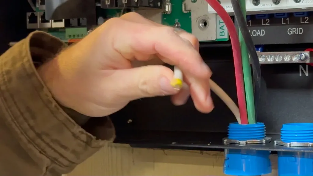
After hearing the click, I knew the connections were properly torqued. I verified my phase wiring, noting that while standard American electrical systems use black for L1 and red for L2, I had started mine differently. I decided to roll with my existing setup since the grounds, neutrals, and phases were all correctly landed and torqued.
Removing Redundant Battery Splices
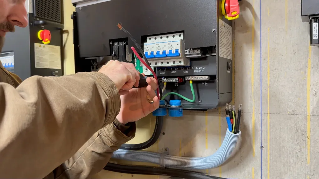
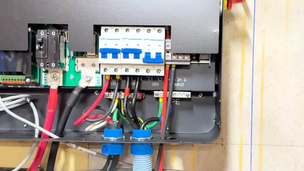
I turned my attention to the battery cables, specifically removing a splice I no longer needed. I took off the cover to expose the connection point. While I considered adding a new lug, I decided to keep the existing cable length for now, as replacing the entire run would have made the cables too short for my current layout.
Connecting Battery Cables
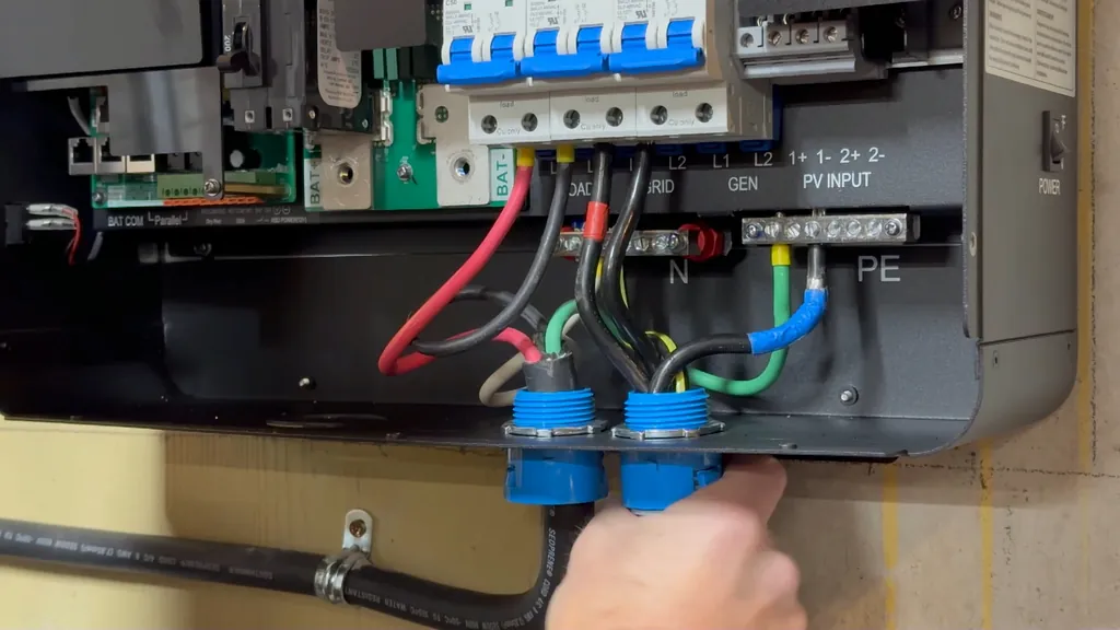
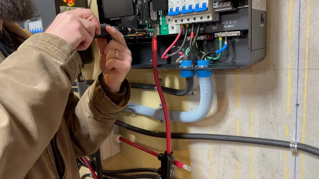
I used an Allen key to secure the battery cable into the terminal. I taped the connection to keep dust and debris out of the exposed area. For the final tightening, I used a 10mm socket, aiming for 40 inch-pounds (4-5 Newton meters) to ensure a solid contact.
Routing Negative Battery Cables
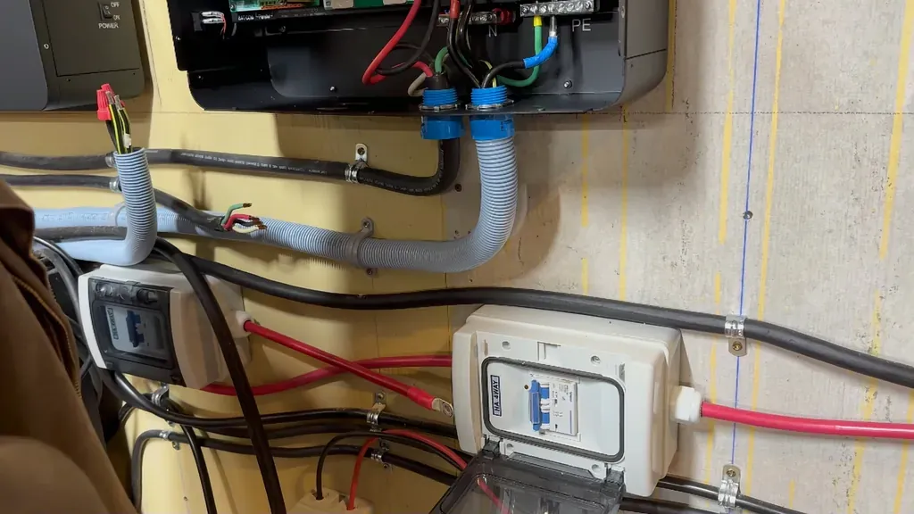
I carefully connected the negative battery cable, keeping it well away from the positive terminal to avoid any accidental short circuits. I left the PV connections for later, as my solar panels weren't positioned yet. This allowed me to move on to the next inverter in the chain.
Comparing Wire Flexibility
I noticed a major difference in how easy it was to work with the high-quality copper wire compared to the aluminum I had used previously. The flexibility made it much faster to route and seat the cables into the terminal blocks. It took me about 10 minutes to get the remaining units snugged down and ready for final torque checks.
Configuring Parallel Dip Switches
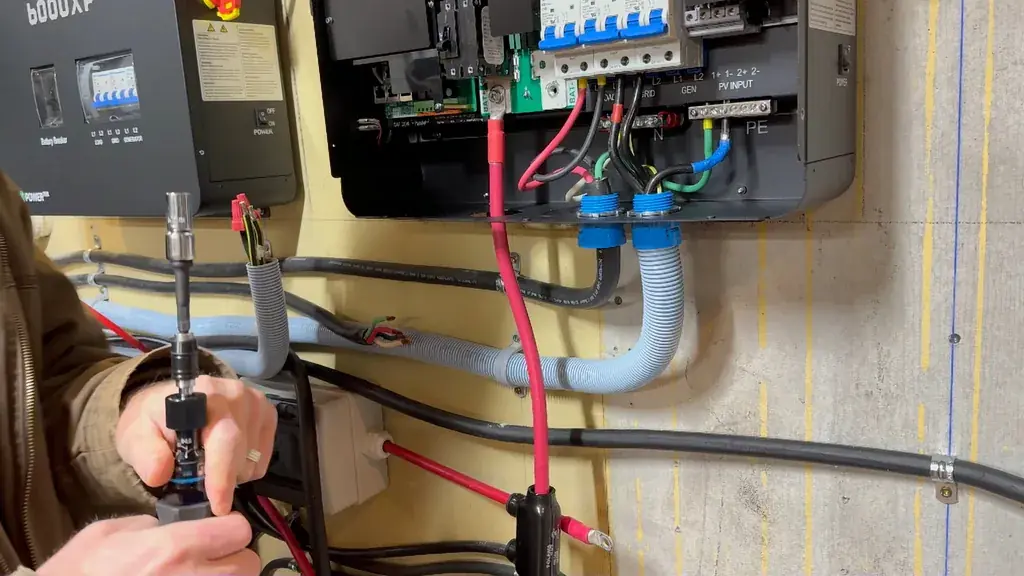
To run the inverters in parallel, I had to set the dip switches on each unit. For my three-inverter setup, the first unit on the left gets both switches in the up position. The middle unit has both switches down, and the final unit has both switches up again.
Connecting Communication Cables
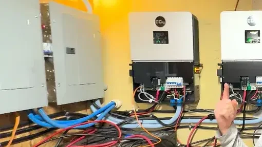
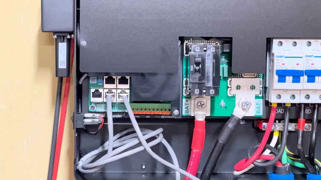
I daisy-chained the communication cables by running the right port of one unit to the left port of the next. I ignored the orange battery cable during this phase, focusing only on the gray communication lines. This loop ensures all three inverters share data correctly for parallel operation.
Installing PV Isolators
I installed isolators on the wall to allow for safe disconnection of the PV lines. This gives me a clear way to cut power to the inverters while I'm working on the connections. I also connected the orange cable from the master inverter to my LifePower4 battery bank to complete the data link.
Finalizing System Commissioning
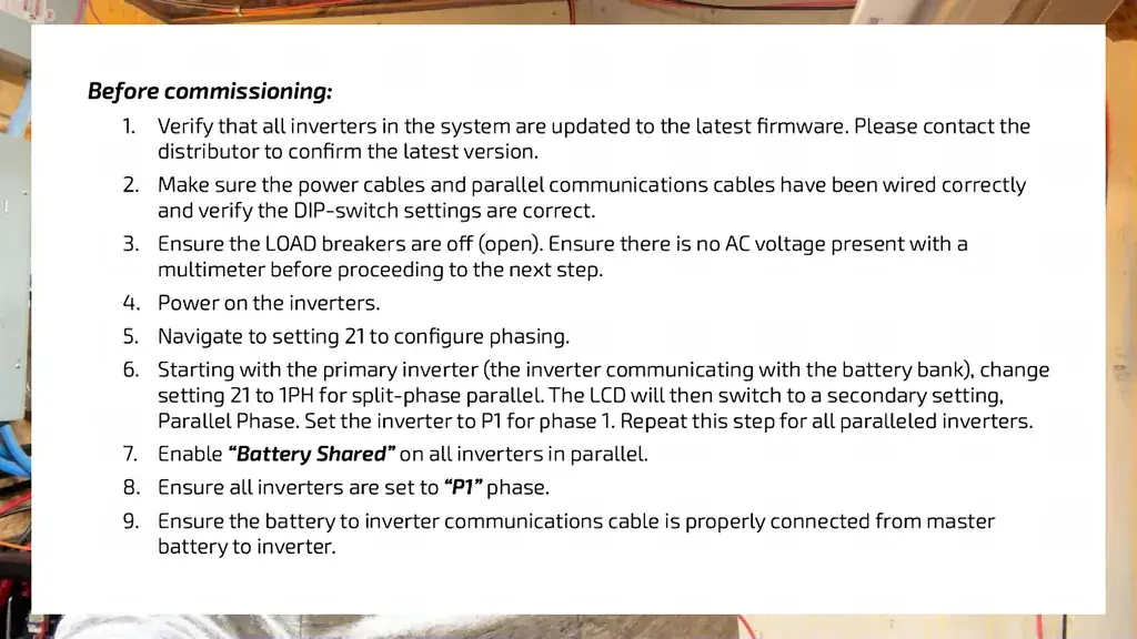
I followed the commissioning procedures in the manual to set the inverters to parallel mode. These 6000XP units have built-in switchgear that makes the process much simpler than my previous setup. I've found these inverters to be flawless once I worked through a few initial bugs.
Reviewing System Performance
I'm planning to share a follow-up video detailing the specific things I love and hate about these units. Even with their solid performance, there are a few quirks I've encountered that are worth discussing. I appreciate all the feedback and questions you've left in the comments so far.
⚠️ CAUTION: SAFETY WARNING!
Always disconnect all power sources, including PV and battery inputs, before touching terminal blocks. Verify zero voltage with a multimeter before performing any adjustments.
Summary & Tips
This upgrade to the EG4 6000XP system has been a significant improvement for my off-grid setup. The built-in switchgear and improved terminal design made the installation process much more manageable than my previous configuration. I'm satisfied with how the system is running and look forward to testing it under heavier loads. I'll be sharing more details on the specific pros and cons in my next update.
📋 FAQ
❓ Do I really need to use ferrules on these wires?
Yes, the manufacturer manual explicitly requires them for finely stranded wire. They prevent the strands from spreading under the terminal screw, which is critical for maintaining a low-resistance connection. Skipping them could lead to loose wires and localized overheating.
❓ Can I use aluminum wire for these connections?
While aluminum is possible, copper wire is significantly easier to work with due to its flexibility. I found the copper much simpler to route into the tight terminal spaces.
❓ How do I know the torque is correct?
You should use a calibrated torque screwdriver set to the specific value mentioned in the manual, which is 18 inch-pounds for these terminals. Always listen for the click of the tool, as this confirms you have reached the exact pressure required for a safe connection. Never guess or over-tighten, as you could strip the threads or damage the terminal block.
❓ What is the dip switch setting for three inverters?
The configuration follows a 2-up, 2-down, 2-up pattern across the three units. This tells the system how to communicate in a parallel array.
Disclaimer: I purchased all tools for this guide with my own money to ensure an unbiased review. This post contains affiliate links, meaning I earn a small commission if you make a purchase at no extra cost to you.