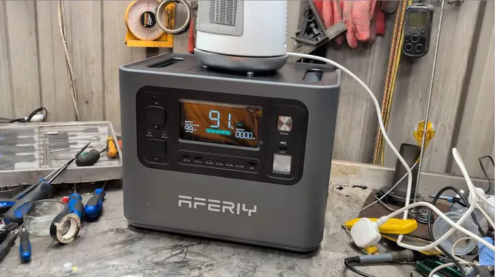
I put the Aferiy P210 power station through rigorous bench testing to measure inverter waveform quality, earth ground path integrity, DC high-amperage output, and outlet spacing. Oscilloscope analysis confirmed pure sine wave stability under heavy resistive heating loads. Multimeter checks verified continuous ground pass-through from the AC inlet to the output sockets, while high-current testing revealed the inverter’s voltage regulation behavior during extreme surge events.
⚡ Quick Guide: How to Make It in 15 Steps
- Verify AC sine wave on oscilloscope under resistive load.
- Check earth continuity from IEC inlet to outlet pin.
- Probe live and neutral floating states with multimeter.
- Inspect 12V cigarette lighter and XT60 output specs.
- Examine front panel DC terminal safety connector orientation.
- Connect diesel heater to measure startup amp draw.
- Hook up USB tester to check 5V rail stability.
- Increase USB dummy load current to 2 amps.
- Test UK plug clearance across tightly spaced sockets.
- Insert secondary power cord into narrow socket bay.
- Apply 1kW to 2kW resistive load to inverter.
- Push AC inverter load past 2400W nominal capacity.
- Measure AC output voltage sag under overload conditions.
- Verify 13V regulated DC rail under heavy load.
- Inspect emergency LED panel function and overall specs.
📋 In This Article
- Technical Specifications & Components
- Tools & Materials Used — what you will need for this project
- Verifying Sine Wave Output Under Resistive Load
- Checking Ground Continuity Across Internal Wiring
- Evaluating Inverter Grounding and Floating Neutral States
- Inspecting High-Current DC Terminals and Port Layout
- Analyzing Front Panel High-Voltage Terminal Safety Defect
- Testing Diesel Heater Cold Startup Draw Limits
- Validating Regulated 13V DC Output and USB Rail Stability
- Escalating USB Current Loads on Front Panel Ports
- Identifying Physical AC Outlet Clearance Deficiencies
- Forcing Dual High-Load Connectors for Inverter Stress Test
- Ramping AC Inverter Load Up to 2000 Watts
- Testing Inverter Overload Behavior Beyond 2.4kW
- Measuring AC Voltage Sag Under Heavy Overload Conditions
- Synthesizing DC and AC Rail Bench Test Results
- Evaluating Emergency Lighting and Final Bench Verdict
- FAQ
📊 Technical Specifications & Components
| Inverter Rated Continuous Power | 2400 Watts |
| AC Output Waveform | Pure Sine Wave (Verified via Scope) |
| Earth Ground Pass-Through Continuity | True direct connection (0.0 Ohms) |
| High-Current DC Port | XT60 12V Nominal (25A Max) |
| Auxiliary DC Socket | 12V Cigarette Lighter Socket (10A Regulated) |
| Regulated DC Voltage Output | Constant 13.0V DC under load |
| AC Voltage Sag Behavior | Drops from 228V AC to 194V AC near 2.4kW threshold |
| USB Low-Voltage Outputs | USB-A / USB-C 5V up to 2A tested |
| Integrated Lighting | Multi-mode LED Panel (Solid, SOS, Strobe) |
📊 Project Overview & Costs
🔧 Difficulty Level: Easy
⏱️ Time Investment: DIY: 30 minutes | Pro: 15 minutes
💰 Professional Service Cost: $50 - $100
💡 Verdict: Performing bench diagnostic verification on power station specs reveals true load limits before deployment in off-grid setups.
🛠️ Tools & Materials Used
• Halogen Resistive Heater Load
• USB Electronic Load Tester
• Modified UK 3-Pin Test Adapter
• Hcalory 12V Diesel Heater
• XT60 Connector Cable Assembly
Real-World Testing and Results
Verifying Sine Wave Output Under Resistive Load
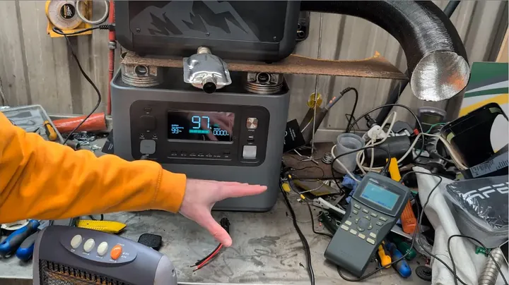
I started by connecting a calibrated oscilloscope to the AC ports. Pure sine wave integrity is vital for charging sensitive electronics or powering inductive tools. I used a high-draw halogen heater to create a consistent resistive load for testing. After flipping the AC inverter on, I adjusted the scope settings to get a clear view. The wave appeared clean. It stayed smooth and stable, free from clipping or harmonic distortion, even as the load pushed past 1200 watts.
Checking Ground Continuity Across Internal Wiring
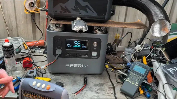
Manufacturers often cut corners on grounding in portable units. I needed to confirm if the earth pin on the rear IEC inlet connects directly to the front AC outlets. I built a custom 3-pin plug shell with exposed pins to probe the circuit safely. I set my multimeter to continuity mode. I placed one probe on the IEC ground terminal and the other on the output ground pin to verify the connection.
Evaluating Inverter Grounding and Floating Neutral States
The meter gave a clear tone. Continuity is confirmed. The ground path is solid from the input all the way to the output. While operating in off-grid mode, the neutral and live lines remain floating relative to ground. There is no potential difference to ground unless a secondary path is created. It's a safe design. Once finished, I closed the plug housing to prevent any stray contact.
Inspecting High-Current DC Terminals and Port Layout
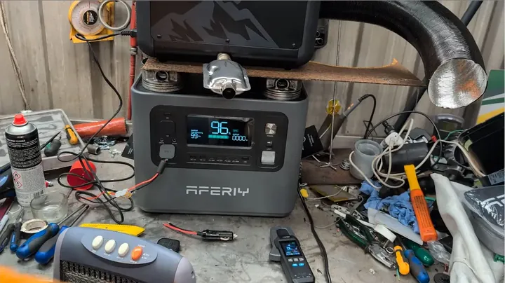
I examined the front DC ports to evaluate their utility for powering off-grid gear like diesel heaters. The unit includes a standard 12V cigarette outlet and an XT60 connector rated for 25A. That XT60 port is excellent for handling high-draw startup sequences. Standard cigarette lighter sockets often fail under sustained loads because their spring contacts lose tension. The XT60 is a much more robust choice for high-current applications.
Analyzing Front Panel High-Voltage Terminal Safety Defect
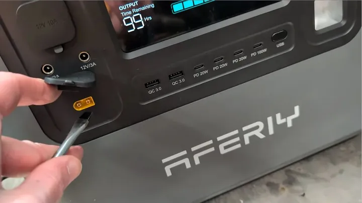
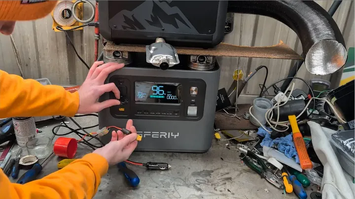
I noticed an issue with the XT60 mounting. The panel features exposed male pins. This is a design flaw. Power-providing ports should use recessed female contacts to avoid accidental shorting. If a metal tool or key touches those pins while the power is active, it will cause an immediate short circuit, blowing an internal fuse. This is a clear oversight in the panel layout. The design should prioritize recessed female sockets for safety.
Testing Diesel Heater Cold Startup Draw Limits
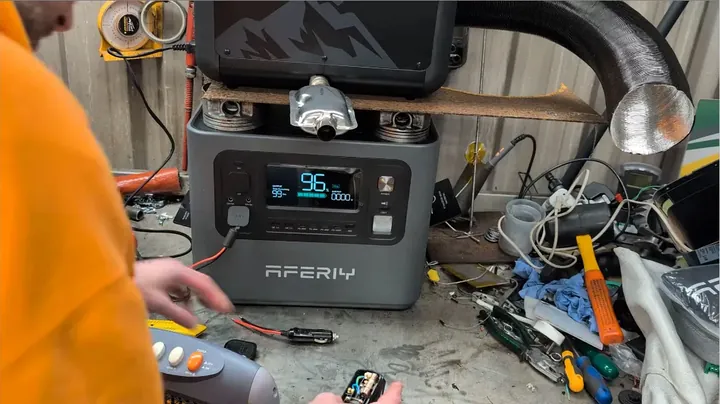
I attached an Hcalory 12V diesel heater to test the DC circuit's capability. Diesel heaters draw significant power during ignition to heat the ceramic glow plug. I connected the heater to the XT60 port, activated the DC power, and started the ignition cycle. The heater pulled 8.2 amps at peak before stabilizing. Both the cigarette port and the XT60 terminal handled the surge without issue.
Validating Regulated 13V DC Output and USB Rail Stability
I monitored the DC rail during the heater's ignition phase. The internal converter provided a stable 13.0V output throughout the process. Many units struggle here, allowing voltage to drop toward 10V and triggering shutdowns, but the Aferiy held steady. Next, I tested the USB-C rail stability using an inline power meter to ensure the logic board regulates low-voltage outputs properly.
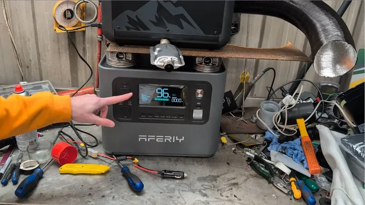
Escalating USB Current Loads on Front Panel Ports
I applied a 1-amp load to the USB-C port, and the voltage remained constant at 5.0V. Increasing the load to 2 amps didn't change the reading. The internal regulation seems clean for standard charging tasks. I didn't have the equipment to reach the 100W PD threshold, but for mobile devices, the 5V output remains reliable and noise-free.
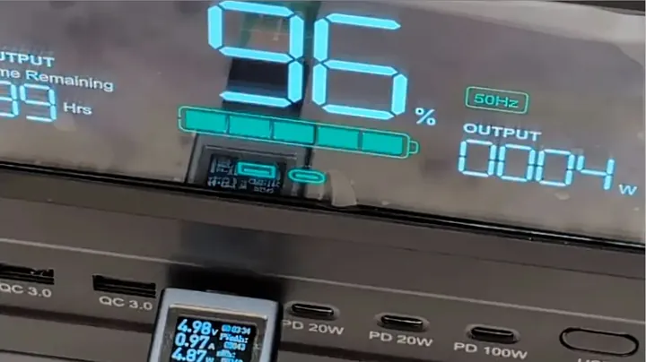
Identifying Physical AC Outlet Clearance Deficiencies
I found a significant design issue with the AC outlets. The sockets are recessed deep into the panel with very narrow spacing. While standard slim plugs fit individually, larger plugs with angled boots or bulky housing hit the edge of the casing. Trying to use two adjacent outlets often results in one plug failing to seat properly. The tight geometry limits the actual utility of the three provided ports.
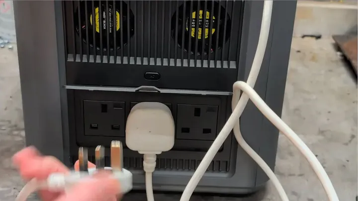
Forcing Dual High-Load Connectors for Inverter Stress Test
To continue testing, I wedged a slim plug and a bulkier winged plug into the adjacent outlets. It's a tight, awkward fit. While it allows current to flow, the proximity issue is a poor design choice. Users need better clearance to utilize multiple outlets simultaneously. An extra 15mm of spacing or a flatter faceplate would resolve these interference problems entirely.
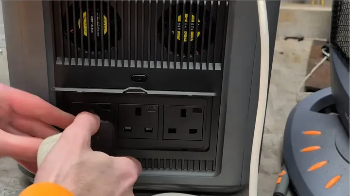
Ramping AC Inverter Load Up to 2000 Watts
I activated the load bank to test the inverter's capacity. I started with a 1kW load and then engaged the second heater stage to reach a 2000W continuous draw. The digital display immediately showed the load increasing to 2000W. I positioned the heaters carefully to ensure the heat didn't damage any nearby equipment. The internal fans engaged quickly to handle the thermal load.
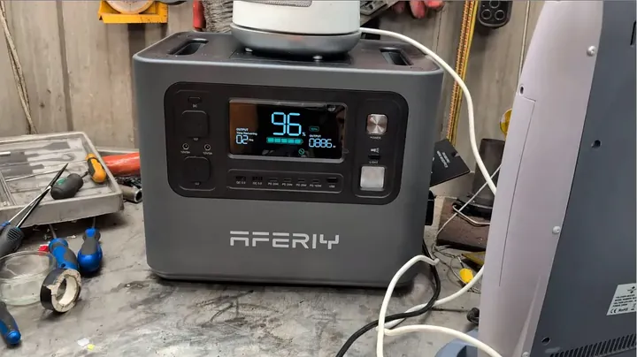
Testing Inverter Overload Behavior Beyond 2.4kW
I added another 1200W load to push the total draw well beyond the 2400W nominal rating. I wanted to see how the inverter handles extreme over-capacity. Many units will instantly cut power if you exceed their rating by even a few percent. The Aferiy, however, uses a different approach: it throttles the output voltage to keep the current from causing a hard shutdown.
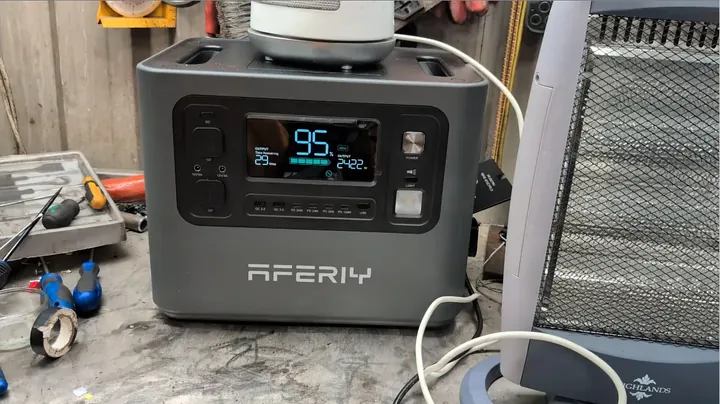
Measuring AC Voltage Sag Under Heavy Overload Conditions
I measured the output voltage with a multimeter during the 2.4kW+ overload test. The base voltage was 228.4V. At a 2kW load, it stayed at 226V. But at 3.4kW, the inverter pulled the voltage down to 194V to keep the current under the 2.4kW limit. It sags quickly. While this prevents a total power cut, it could cause issues for motors or other devices that require a steady voltage.
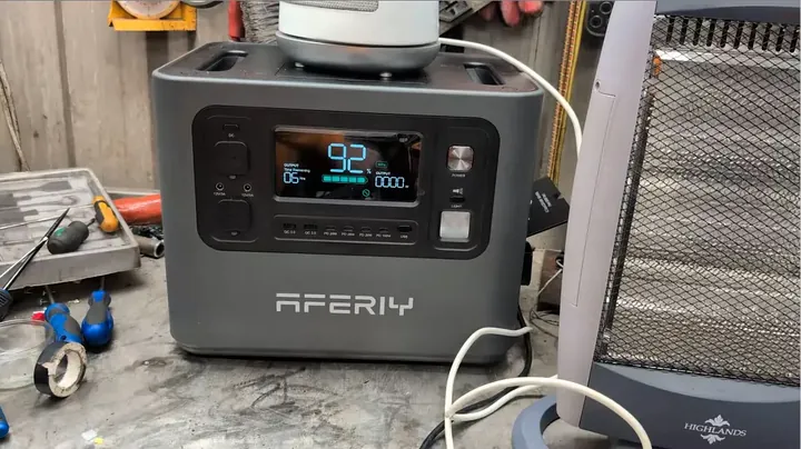
Synthesizing DC and AC Rail Bench Test Results
I summarized my data from the various tests. The 13V DC output is very consistent, effectively handling heater ignition surges. The USB rails provide clean, stable 5V power. The inverter generates a true sine wave and meets its 2400W continuous rating, though it achieves this under extreme conditions by throttling the AC voltage output rather than shutting down. Overall, the performance is solid for its class.
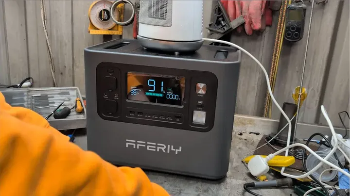
Evaluating Emergency Lighting and Final Bench Verdict
I finished by checking the LED panel. The light is bright and includes several modes like SOS and strobe, which is handy for emergencies. The Aferiy unit is well-built for off-grid demands. The grounding and the stable 13V rail are its best features. Just watch out for the cramped outlet spacing and the exposed pins on the DC interface.
⚠️ CAUTION: SAFETY WARNING!
Working around exposed AC output leads during load testing poses severe shock and electrocution hazards. Always ensure AC inverter power is switched off before adjusting test probes or modified plug assemblies.
Summary & Tips
The Aferiy P210 performs reliably, maintaining a clean sine wave and consistent ground path. Its 13V rail is excellent for powering diesel heaters without failure. However, the tight outlet spacing makes using multiple plugs difficult. Despite a few design flaws in the panel layout, it remains a capable unit for demanding off-grid power needs.
📋 FAQ
❓ Is the AC output on the Aferiy P210 a true pure sine wave?
Yes, oscilloscope testing confirms a clean pure sine wave under both moderate and heavy loads. The waveform is consistent and free from distortion, ensuring safety for sensitive electronics.
❓ Can this power station start and run a 12V diesel heater?
Yes, it handles the task well. The 13V regulated DC output is stable enough to manage the ignition current of a diesel heater without triggering an overload shutoff.
❓ Does earth ground pass all the way through the unit?
It does. Testing confirms a direct, continuous path from the AC charging inlet ground to the output socket ground pins.
❓ What happens when you exceed the 2400W AC output limit?
The system throttles output voltage rather than shutting down. While this keeps resistive devices running, it can cause performance issues for motor-driven tools.
Disclaimer: I purchased all tools for this guide with my own money to ensure an unbiased review. This post contains affiliate links, meaning I earn a small commission if you make a purchase at no extra cost to you.