The Anker Solix C1000 Gen 2 power station features a dense internal layout designed for high-capacity energy storage. This teardown reveals the structural assembly, BMS configuration, and component-level integration of the unit. We examine the chassis, PCB layout, and battery pack construction to understand how Anker manages thermal and electrical distribution within this portable power system.
⚡ Quick Guide: How to Access Internal Components
- Remove the rubber feet to locate hidden chassis screws.
- Carefully separate the side panels to reveal the internal frame.
- Disconnect the front panel and main PCB communication cables.
- Extract the battery pack by unscrewing the internal mounting points.
- Inspect the BMS wiring and thermistor placements for maintenance.
📋 In This Article
- Technical Specifications & Components
- Tools & Materials Used — what you will need for this project
- Accessing the Chassis Fasteners
- Inspecting Internal Vibration Mitigation
- Removing the Front Panel Assembly
- Disconnecting Internal Wiring Harnesses
- Analyzing the Main Control Board
- Evaluating PCB Conformal Coating
- Extracting the Secondary PCB
- Accessing the Battery Pack
- Inspecting Cooling Fans and Sensors
- Analyzing Mains and Load Sensing
- BMS Communication and Battery Terminals
- Removing the Battery Pack
- Analyzing Cell Configuration and Thermistors
- Testing Battery Pack Voltage
- Final Inspection and Reassembly
- FAQ
📊 Technical Specifications & Components
| Battery Chemistry | LiFePO4 |
| Battery Capacity | 16-cell configuration |
| BMS Monitoring | Multi-point NTC thermistors |
| Output Architecture | Multi-relay switching |
| Cooling System | Dual speed-sensitive fans (Evercool) |
| Chassis Material | Polycarbonate ABS |
| Voltage (Measured) | 51.95V (Battery Pack) |
| Charging Ports | Main DC input and Solar/12V input |
📊 Project Overview & Costs
🔧 Difficulty Level: Hard
⏱️ Time Investment: DIY: 2-3 hours | Pro: 1 hour
💰 Professional Service Cost: $150-$200
💡 Verdict: Performing this teardown yourself provides deep insight into repairability but voids the manufacturer warranty.
🛠️ Tools & Materials Used
• Spudger
• Precision Tweezers
• Wire Cutters
Step-by-Step Assembly, Repair, Testing & Inspection
Accessing the Chassis Fasteners
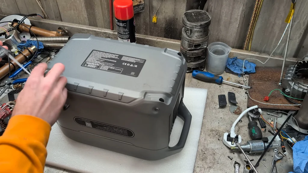
The Anker Solix C1000 Gen 2 is designed with a deceptive exterior. It features plastic hex-shaped fasteners on the sides that appear to be molded into the casing. These are purely cosmetic. To gain entry, you must peel back the rubber feet located on the base. Underneath, you will find the actual screws holding the unit together. It's a tight fit. Keep these feet somewhere safe so you don't lose them during the process.
Inspecting Internal Vibration Mitigation
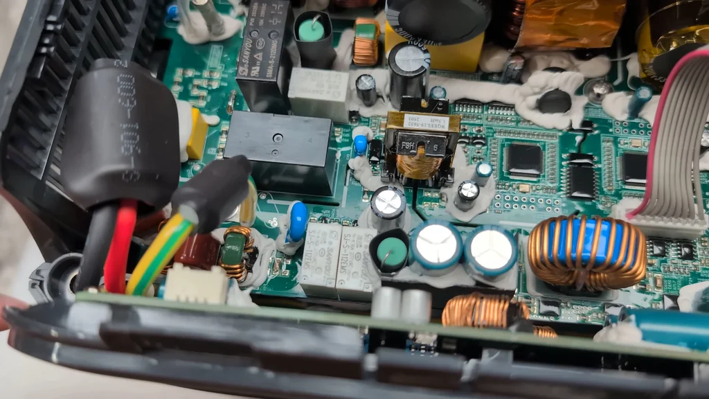
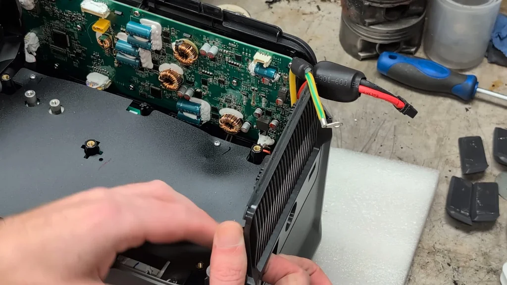
Once the outer shell is loose, you'll notice the internal construction is heavily reinforced. The manufacturer has used a significant amount of potting compound, or 'gloop', to mitigate vibration for the internal components. You will also see extensive use of Kapton tape protecting sensitive areas like capacitors. Earth bonding wires are routed throughout the assembly to ensure chassis grounding. It's well-protected. The front panel connections are tucked away beneath the primary board assembly.
Removing the Front Panel Assembly
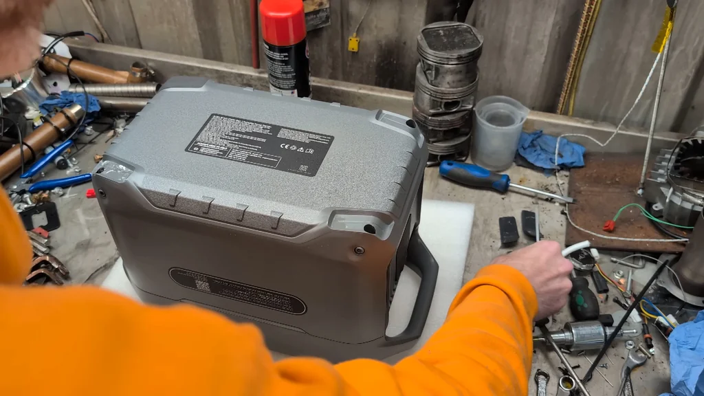
The front panel design allows for removal without fully stripping the side chassis. You need to carefully unplug the communication cables from the main board. It's a delicate operation. The side vents are integrated into the main shell, so don't force them. Once the screws are removed, the panel should lift out. In theory, this provides access to the primary control interface.
Disconnecting Internal Wiring Harnesses
After the initial screws are out, the board should feel loose. You must snip the cable ties holding the wire looms together to gain enough slack for extraction. Ensure all connectors are fully detached from the main PCB. It's not attached anymore. You might find resistance near the XT connector side, where the mains and switch wiring are routed. Check the reset switch for any hidden fasteners before pulling the assembly out.
Analyzing the Main Control Board
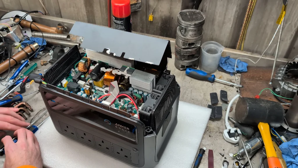
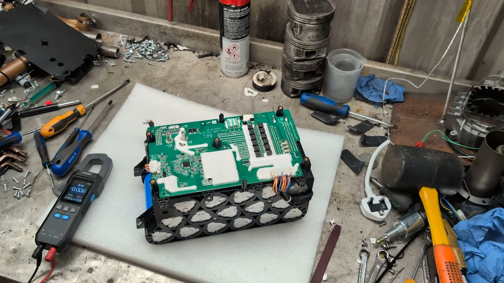
With the plastic tray removed, the main board is fully exposed. You can clearly identify the toroidal inductors, transformers, and power relays. There is a prominent main fuse located on the board for overcurrent protection. Suppression capacitors are also visible, likely for EMI filtering. It's a complex layout. This board manages the power conversion and charging logic for the entire station.
Evaluating PCB Conformal Coating
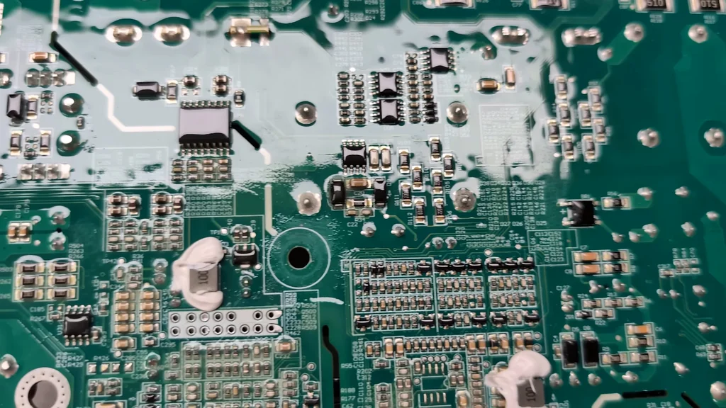
The board is protected by a remarkably thick layer of conformal coating. This is essential for preventing short circuits from moisture or dust. The component density is quite high, featuring numerous surface-mount devices. It's impressive work. You can identify the main charging port and the solar/12V input circuitry. If a component fails, you would need a high-quality microscope to perform any board-level repair.
Extracting the Secondary PCB
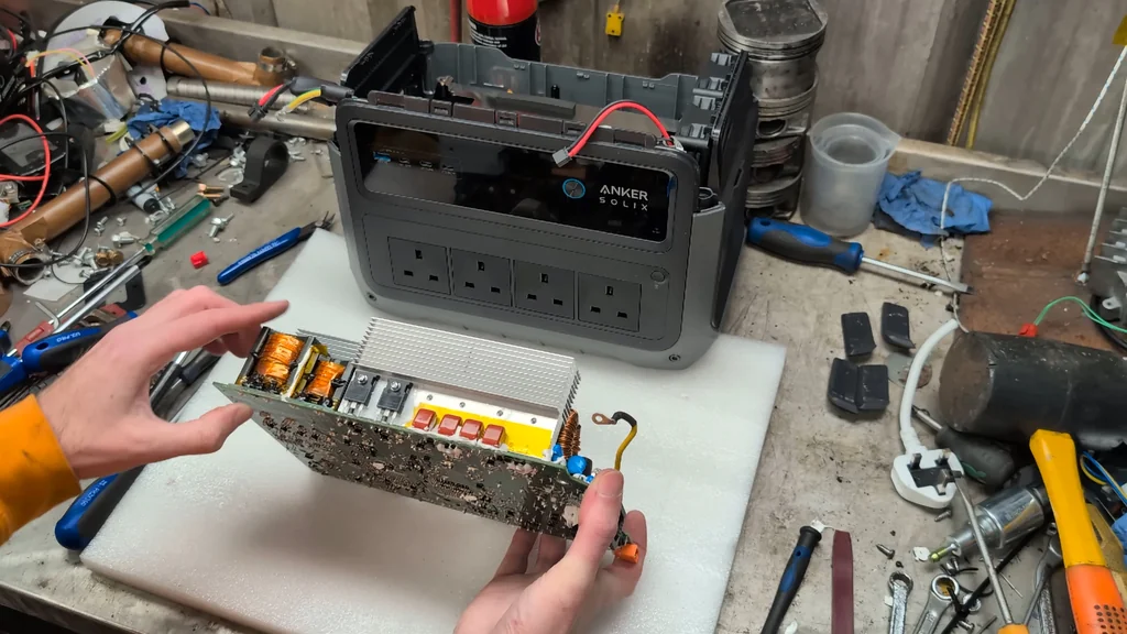
The secondary board hosts a large array of capacitors and heavy-duty windings. Kapton tape is used here again to prevent accidental conduction between components. These windings are quite monstrous. Once you've cleared the board, you can access the front panel and the battery pack. It's a straightforward modular design. Just take care when removing the cover to avoid damaging the underlying sensors.
Accessing the Battery Pack
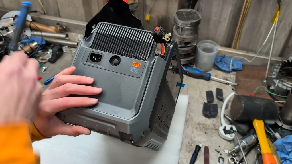
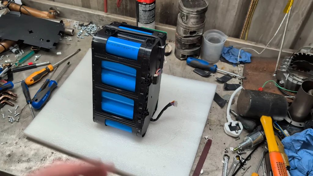
The side panels clip on securely, requiring a bit of leverage to pop them off. Once removed, the battery pack is finally visible. It's a large, integrated unit. You'll also find the 12V socket and the power button assembly on this side. The button features an integrated LED indicator. It's a clean design. The whole assembly pops out once the final screws are cleared.
Inspecting Cooling Fans and Sensors
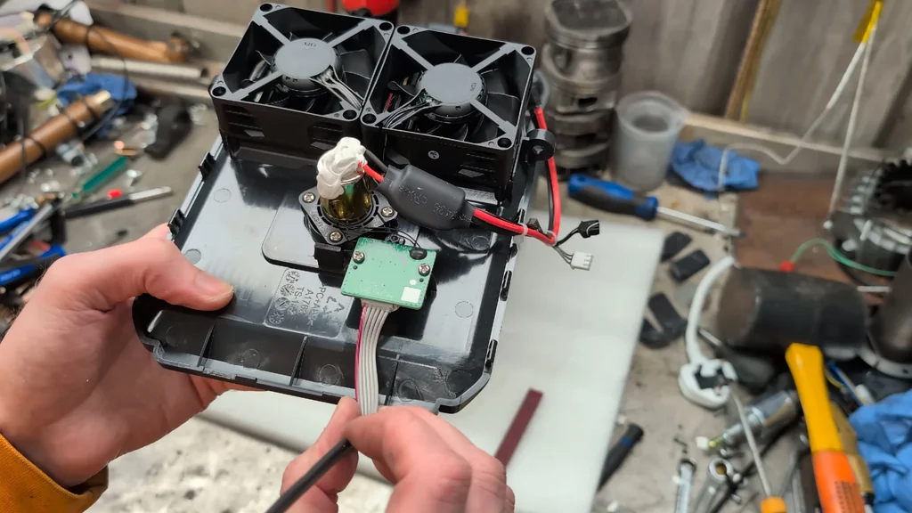
The cooling system uses two speed-sensitive fans from Evercool. These fans include integrated speed sensors for the BMS to monitor airflow. Each fan is held in place by small screws. It's a smart setup. The front panel communication uses a six-wire interface to handle the switch, LED, and various sensors. These connections are tight, so use a spudger to avoid snapping the plastic clips.
Analyzing Mains and Load Sensing
The UK mains outlets are all linked to a common earth bus. The mains input track is clearly visible on the board. There is a specific sensor line that appears to track the load. It's hard to remove. This sensor is likely responsible for the real-time power monitoring displayed on the screen. The integration here is very tight.
BMS Communication and Battery Terminals
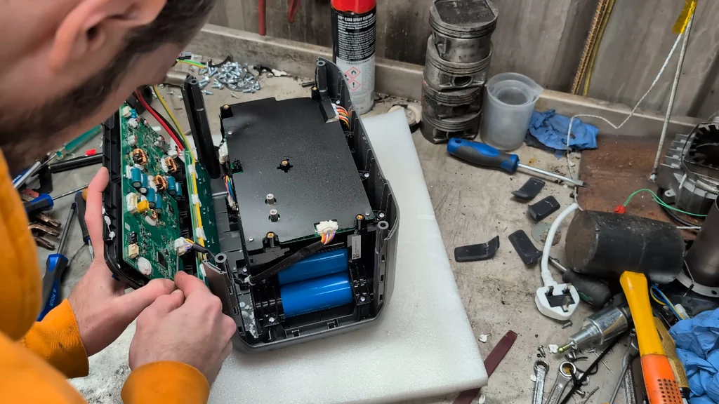
The battery pack communicates with the system via a dedicated BMS cable. You can see the main power positive and negative terminals clearly labeled. The plastic housing is made of polycarbonate ABS. It's very durable. Once you unstick the protective tape, the main battery terminals are accessible for voltage testing. The communication protocol is proprietary, so don't expect standard pinouts.

Removing the Battery Pack
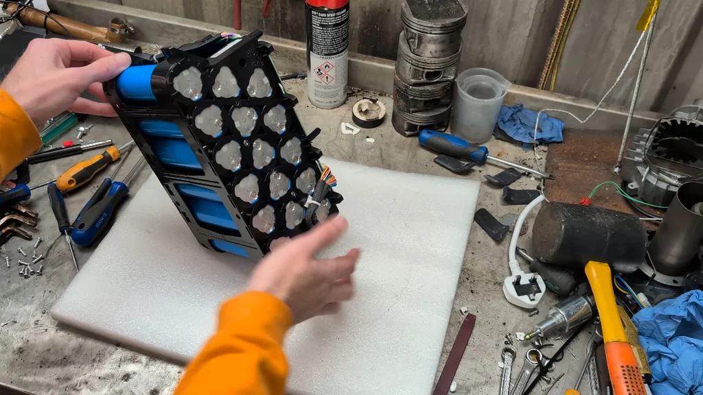
The screws holding the battery pack are not magnetized, but they are the correct size for the driver. This makes removal much easier. It's a tight fit. You have to wiggle the pack to get it out of the chassis. The battery pack is constructed from polycarbonate ABS, which provides excellent impact resistance. It's a solid piece of kit.
Analyzing Cell Configuration and Thermistors
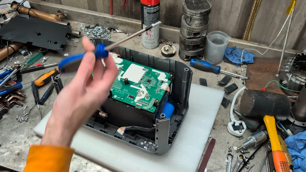
The pack consists of 16 individual cells. It looks like more, but it's just an 8-by-8 arrangement. There is no magic wizardry here. You can see several NTC thermistors (NTC 2, 3, 4) attached to the cells for temperature monitoring. Presumably, there is an NTC 1 somewhere else in the pack. It's a standard safety configuration.
Testing Battery Pack Voltage
With the pack exposed, we can perform a voltage check. The unit arrived with a 20% charge. Using a multimeter, we measure the potential across the battery negative and positive terminals. We get a reading of 51.95V. It's a healthy pack. The voltage should be zero at the main output terminals when the unit is turned off.
Final Inspection and Reassembly
That covers the internal construction of the Anker Solix C1000 Gen 2. We've seen the BMS, the cell layout, and the main board architecture. I'll charge the pack once I've put it all back together. If you have any questions, leave them down below. I'll do my best to answer them. Thanks for watching.
⚠️ CAUTION: SAFETY WARNING!
The battery pack contains high-energy LiFePO4 cells capable of delivering significant current; exercise extreme caution to avoid shorting the terminals. Always discharge the unit and verify zero voltage before performing any internal work.
Summary & Tips
The Anker Solix C1000 Gen 2 demonstrates a robust, modular internal design. Component placement is logical, with clear separation between the AC and DC power stages. The use of vibration-dampening compound and conformal coating reflects a focus on long-term durability. It remains a well-engineered system for those interested in high-capacity portable power.
📋 FAQ
❓ Is the battery pack user-replaceable?
Technically, yes, but it is not intended for end-user service. You would need to disassemble the entire chassis to reach the terminals. It's not a simple swap.
❓ What is the purpose of the Kapton tape inside?
It provides electrical insulation for sensitive components. It also helps secure wiring looms in place. It's a standard practice for high-density electronics.
❓ Can I upgrade the cooling fans?
You could, but they are speed-sensitive and communicate with the BMS. Replacing them with generic fans might trigger an error. Stick to the original specs.
❓ Why are there so many thermistors?
Temperature monitoring is critical for LiFePO4 safety. Multiple sensors ensure the BMS can detect localized heating. It prevents thermal runaway.
Disclaimer: I purchased all tools for this guide with my own money to ensure an unbiased review. This post contains affiliate links, meaning I earn a small commission if you make a purchase at no extra cost to you.