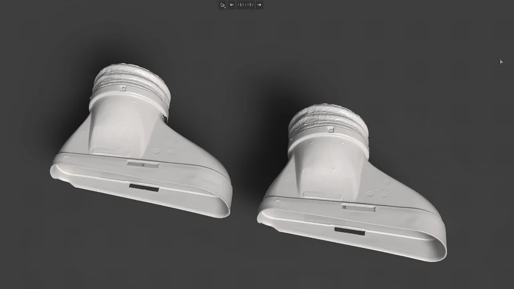
Building a functional harmonic drive from scratch is a serious engineering challenge that avoids the high cost of industrial gearboxes. By utilizing 3D-printed components and specific flexible materials like TPU, you can achieve high gear reduction ratios with near-zero backlash. This project demonstrates the design, fabrication, and testing of a compact harmonic drive suitable for precision robotics and high-torque applications.
⚡ Quick Guide: How to Make It in 12 Steps
- Conceptualize the robotic arm base requirements.
- Understand the mechanical advantage of harmonic drive tooth meshing.
- Select NEMA 17 motors and compatible drivers.
- Research gear module theory and ratios.
- Model the assembly in SolidWorks.
- Print components using TPU for the flex spline.
- Assemble the custom 3D-printed gear parts.
- Verify mechanical fitment and rotation.
- Program the microcontroller for test movement.
- Execute torque and repeatability testing.
- Document design improvements for future iterations.
- Finalize the project and share results.
📋 In This Article
- Technical Specifications & Components
- Tools & Materials Used — what you will need for this project
- Planning the Robotic Arm Base
- Understanding Harmonic Drive Mechanics
- Selecting Motors and Drivers
- Design Research and Material Selection
- Modeling in SolidWorks
- 3D Printing and Slicing
- Assembling the Gearbox
- Verifying Mechanical Operation
- Testing the Drive Performance
- Measuring Torque and Consistency
- Refining the Design
- Project Conclusion
- FAQ
📊 Technical Specifications & Components
| Gear Ratio | 30:1 |
| Gear Module | 0.8 |
| Motor Type | NEMA 17 Stepper |
| Driver Type | A4998 |
| Microcontroller | Elegoo Uno R3 |
| Flex Spline Material | TPU |
| Fastening Method | Heat set brass inserts |
| Test Load | 45g (perpendicular) to 280g (30° offset) |
| Output Rotation | 1 full rotation per 30 motor revolutions |
📊 Project Overview & Costs
🔧 Difficulty Level: Hard
⏱️ Time Investment: DIY: 15-20 hours | Pro: 8-10 hours
💰 Professional Service Cost: $150 - $250
💡 Verdict: Building this custom drive saves hundreds compared to purchasing industrial-grade harmonic gear units.
🛠️ Tools & Materials Used
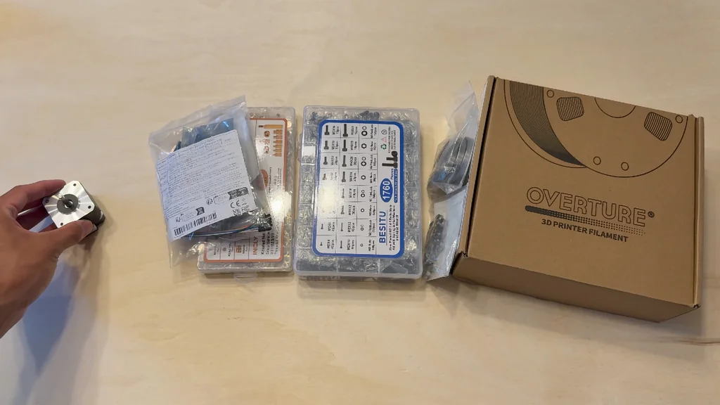
• NEMA 17 Stepper Motor
• A4998 Motor Driver
• Elegoo Uno R3
• Heat set inserts
• Steel screws
• TPU filament
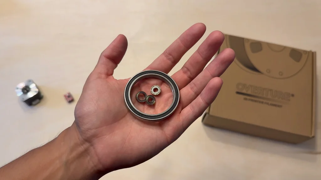
• Large ball bearings
• Small ball bearings
Step-by-Step Assembly, Repair, Testing & Inspection
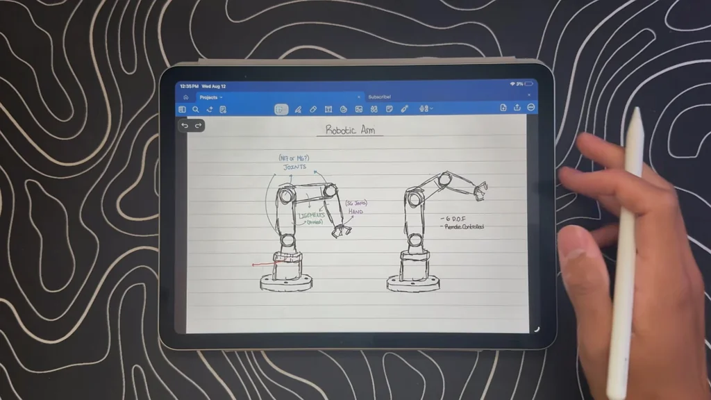
Planning the Robotic Arm Base
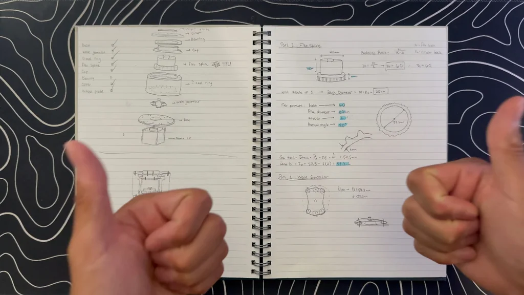
The project begins with a clear objective: creating a high-reduction gearbox for a robotic arm base. Harmonic drives are the standard for these applications because they provide high torque in a small footprint. It's a complex build. I sourced a variety of components to ensure the design would be robust enough for actual operation. The goal is to avoid the high cost of commercial units by fabricating the drive in-house.
Understanding Harmonic Drive Mechanics
Harmonic drives function by keeping gear teeth meshed at two points simultaneously. This geometry eliminates backlash entirely. It's precise. You won't find any sloppy movement or wiggling in a properly designed unit. This makes them perfect for aerospace or high-precision robotics where accuracy is mandatory. They offer massive gear reduction in a very compact space.

Selecting Motors and Drivers
A NEMA 17 stepper motor provides the necessary holding torque for this drive. The motor is useless without a driver, so I chose the A4998 to act as the translator between the controller and the motor. It handles the high current requirements. I also integrated heat set inserts into the 3D-printed parts. Threading steel screws directly into plastic is a failure point. Using a soldering iron to melt brass inserts ensures a permanent, reliable connection.
Design Research and Material Selection
I started the design phase by reviewing gear theory and existing harmonic drive designs. The initial plan called for a module of one and a 30:1 ratio. It failed. The design was far too bulky for my needs. I dropped the module to 0.8 to reduce the footprint. TPU filament is the secret sauce here. It provides the elasticity required for the flex spline component. Without this flexible material, the drive wouldn't function as intended.
Modeling in SolidWorks
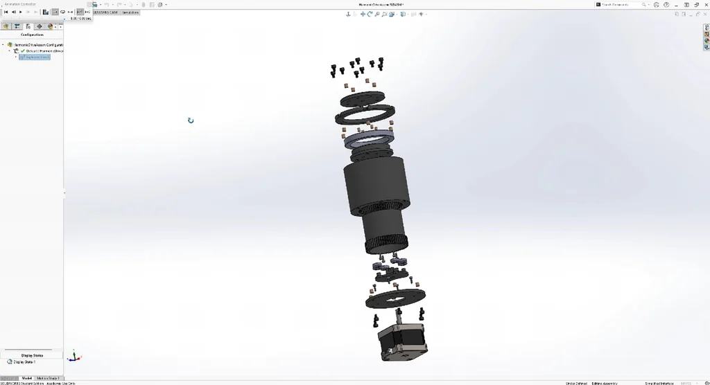
SolidWorks proved invaluable for this stage. I used the built-in gear generation tool to save days of manual drafting. Even with that help, I spent a full week refining the seven custom 3D-printed parts. The design had to be precise. Every component was modeled to work with the purchased bearings and fasteners. It's a tight assembly.
3D Printing and Slicing
Printing the gear teeth required careful slicing parameters. I couldn't make the teeth too small, or the printer would fail to resolve them. I was quite proud of the final design. It printed well on the first try. The TPU component was the most challenging part of the print job. It's a tricky material.
Assembling the Gearbox
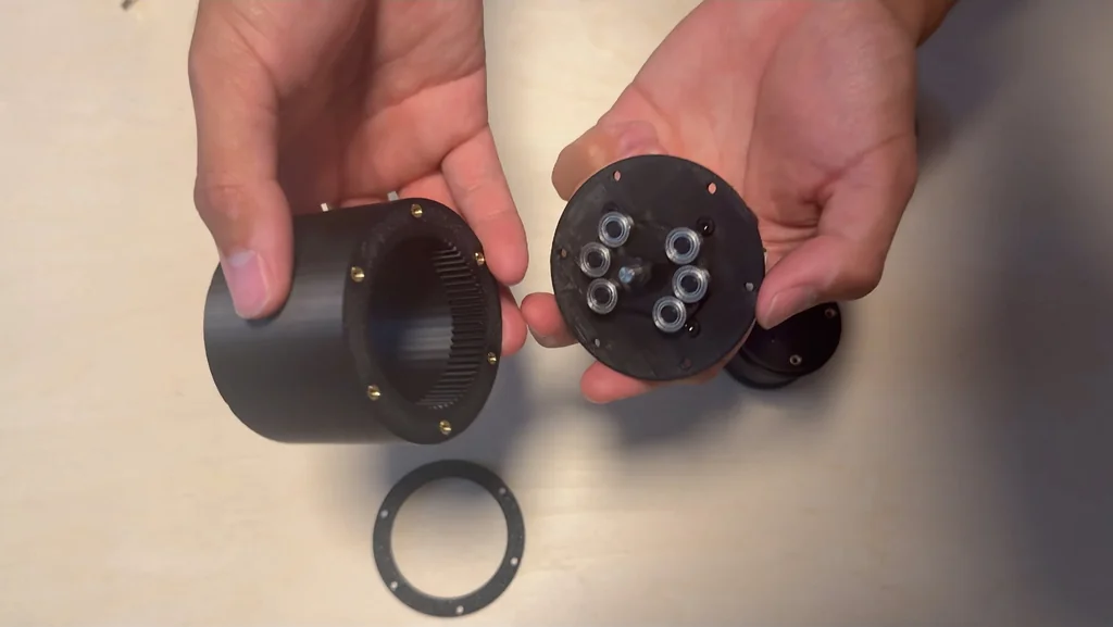
Once the prints were finished, I moved to the assembly phase. The parts fit together as modeled. It was satisfying. I carefully aligned the bearings and the flex spline to ensure smooth operation. The assembly process is straightforward but requires patience to avoid binding.
Verifying Mechanical Operation
The assembly looks solid, but looks can be deceiving. We need to confirm it actually works under load. I checked for any binding or resistance in the gear teeth. It's smooth. The next step is to hook up the electronics and see if the motor can drive the output shaft.
Testing the Drive Performance
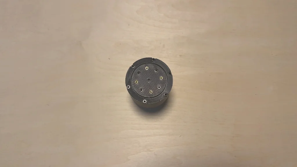
I wrote basic code for the Elegoo Uno to test the drive. It's moving. The first test involved 30 full motor revolutions to verify a single output rotation. If the math is correct, it should hit the mark perfectly. I also needed to test for repeatability. Precision is key.
Measuring Torque and Consistency
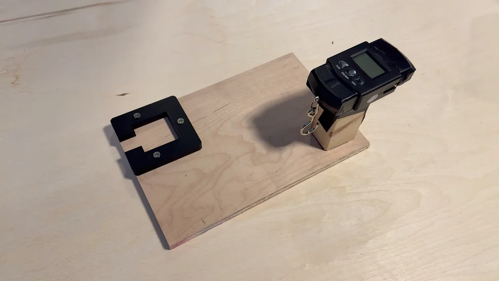
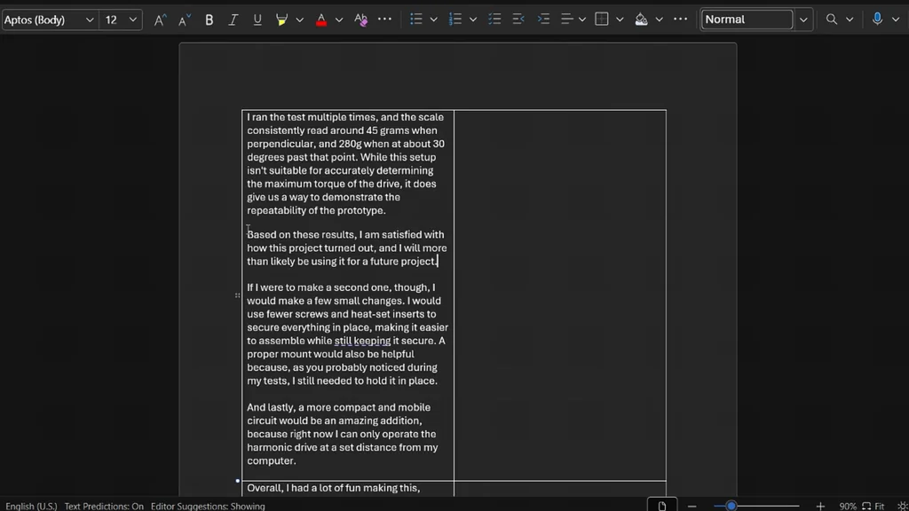
I rigged up a suitcase scale to an arm mounted on the output. I used an elastic band at the 10 cm point to measure force. The scale read 45g when perpendicular. It read 280g at a 30-degree offset. This isn't a professional torque test, but it confirms the drive is functional. It works.
Refining the Design
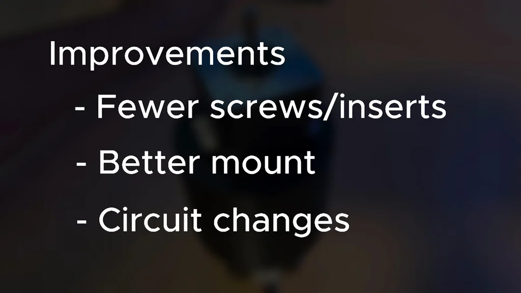
The drive worked on the first try, which was a relief. I would make a few changes for the second version. I'd use fewer screws to simplify assembly. A proper mount is also necessary. Holding it by hand during testing isn't ideal. It's a good start.
Project Conclusion
This build was a great way to learn about new components. I've never used some of these parts before. I hope this helps you build your own harmonic drive. Let me know your feedback in the comments. It's finished.
⚠️ CAUTION: SAFETY WARNING!
Always wear safety glasses when operating 3D printers and handling soldering irons. Be cautious of pinch points when testing the assembled gear drive.
Summary & Tips
The harmonic drive successfully achieved the desired gear reduction. This project proves that high-precision mechanical components can be fabricated with consumer-grade 3D printers. Future iterations will focus on mounting stability and fastener optimization. It was a successful engineering exercise.
📋 FAQ
❓ Why use TPU for the flex spline?
TPU provides the necessary elasticity for the gear to deform and mesh correctly. Rigid materials would simply snap or bind. It's flexible.
❓ Can I use a different motor?
You could, but NEMA 17 is the standard for this size. It's reliable. Just ensure your driver can handle the current requirements.
❓ Is 3D printing gears durable?
It depends on the load and material. For low-torque robotic arms, it's fine. Don't expect industrial longevity.
❓ How do I calculate the gear ratio?
The ratio is determined by the tooth count difference between the flex spline and the circular spline. It's math-heavy. Use CAD software to verify.
Disclaimer: I purchased all tools for this guide with my own money to ensure an unbiased review. This post contains affiliate links, meaning I earn a small commission if you make a purchase at no extra cost to you.