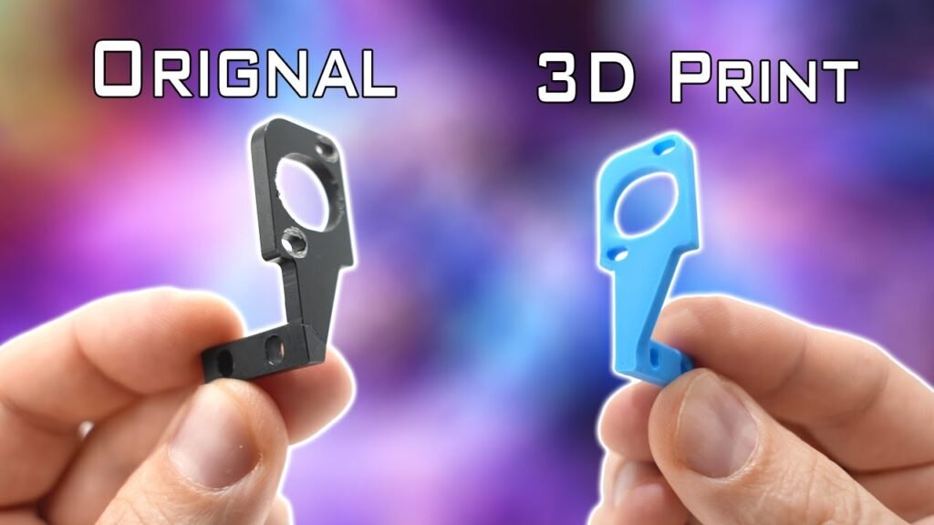
The factory air intake duct on a Mercedes-Benz C250 (W204) often relies on felt materials that trap moisture and debris. Replacing this with a custom-engineered, rigid 3D-printed component is a practical way to improve durability. This guide covers the full workflow from 3D scanning the original part to generating a CAD model in BricsCAD and finally printing a functional replacement using high-temperature filament.
⚡ Quick Guide: How to Make It in 5-10 Steps
📋 In This Article
- Technical Specifications & Components
- Tools & Materials Used — what you will need for this project
- Analyzing the Mercedes-Benz C250 Air Intake
- Scanning with the Creality Sermoon X1
- 3D Scanning with the Creality Pika
- Post-Processing Scan Data
- Comparing Mesh Results
- Evaluating Point Cloud Quality
- Setting Up BricsCAD for Reverse Engineering
- Defining the Sketch Plane
- Creating Tangent Sketches
- Building the Profile Guide Rails
- Adjusting Guide Rail Direction
- Executing the Loft Command
- Refining Surface Smoothness
- Extruding and Trimming Surfaces
- Applying the Shell Command
- Finalizing Geometry and Cutting
- Trimming Locking Slots
- Exporting for 3D Printing
- Printing with the Snapmaker U1
- Opening STEP Files in FreeCAD
- FAQ
📊 Technical Specifications & Components
| Vehicle | Mercedes-Benz C250 (W204 1.8) |
| Scan Resolution | 0.2 mm |
| Noise Removal | 40% default |
| Mesh Face Count | ~5 million |
| Shell Thickness | 2.6 mm |
| Original Part Thickness | 1.9 mm |
| File Format | STEP, DWG, STL |
| Filament | ABS/ASA |
📊 Project Overview & Costs
🔧 Difficulty Level: Hard
⏱️ Time Investment: DIY: 10-15 hours | Pro: 4-6 hours
💰 Professional Service Cost: $400-$600
💡 Verdict: Significant savings over custom fabrication services while gaining a reusable CAD file.
🛠️ Tools & Materials Used
• Creality Sermoon X1 3D Scanner
• Creality Pika 3D Scanner
• BricsCAD Software
• CloudCompare
• Orca Slicer
• Snapmaker U1 3D Printer
• FreeCAD
• ABS or ASA Filament
Step-by-Step Assembly, Repair, Testing & Inspection
Analyzing the Mercedes-Benz C250 Air Intake
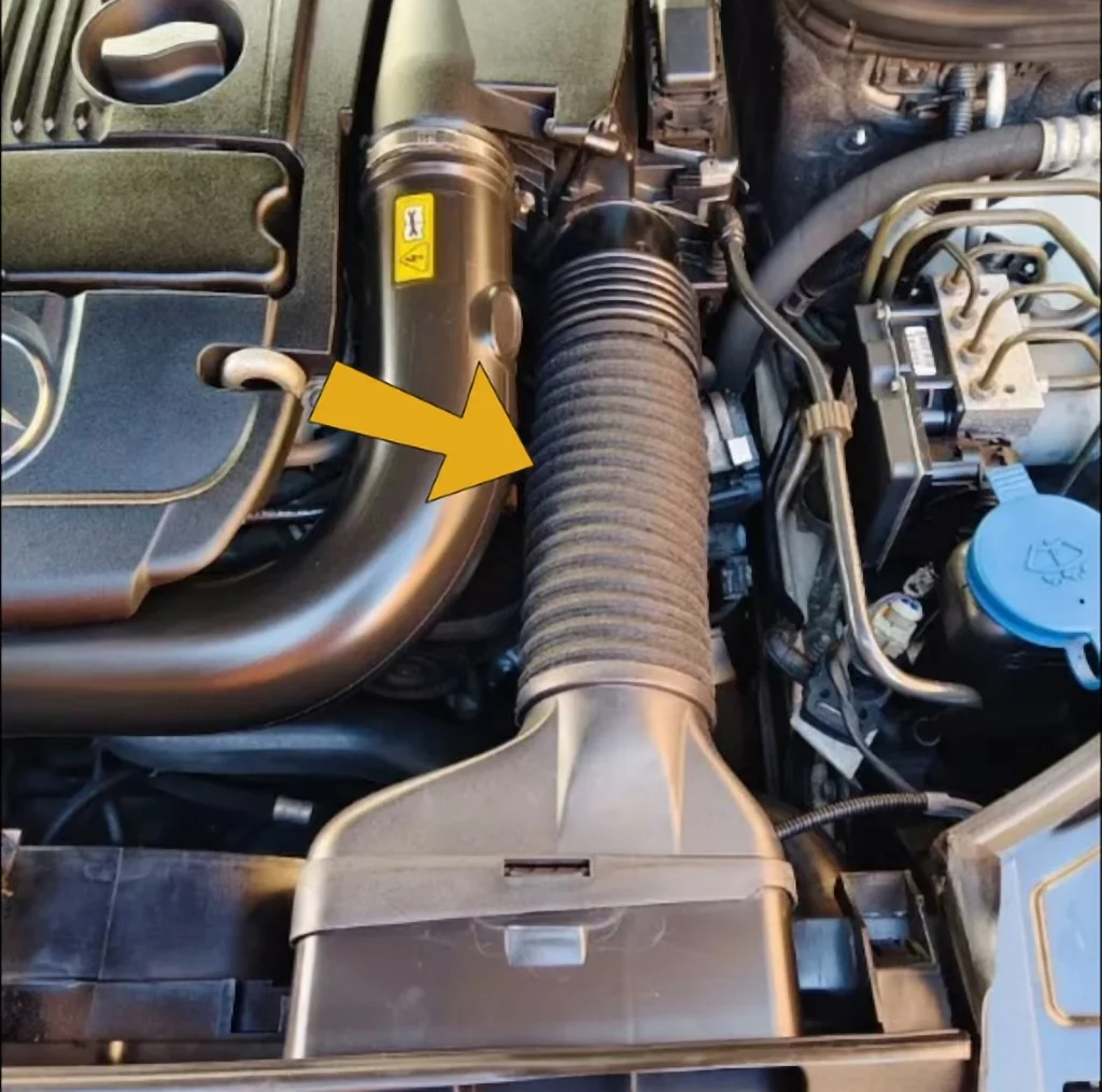
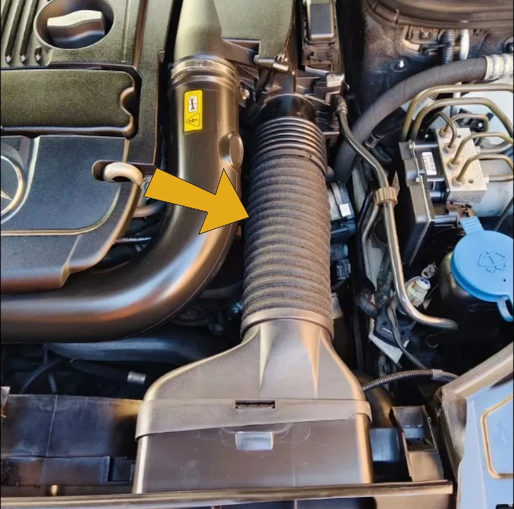
The project begins with a converging duct air inlet from a Mercedes-Benz C250. The aftermarket part currently installed uses felt, which is prone to trapping dust and moisture. It's a poor design. My customer needs a CAD model of this taper inlet to modify it for a different duct configuration. The converging duct connects directly to the air intake system, so precision is mandatory.
Scanning with the Creality Sermoon X1
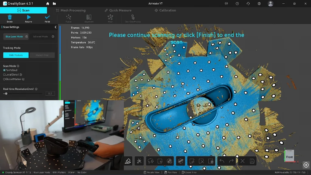
I'm using the Creality Sermoon X1 for the initial scan. It utilizes wide-angle lenses to cover large areas quickly with fewer markers. However, the wide-angle optics struggle to reach into deep pockets compared to other models. To solve this, I switch to the single-line laser mode. It's necessary for deep geometry. Most parts can be fully captured with just two scans.
3D Scanning with the Creality Pika
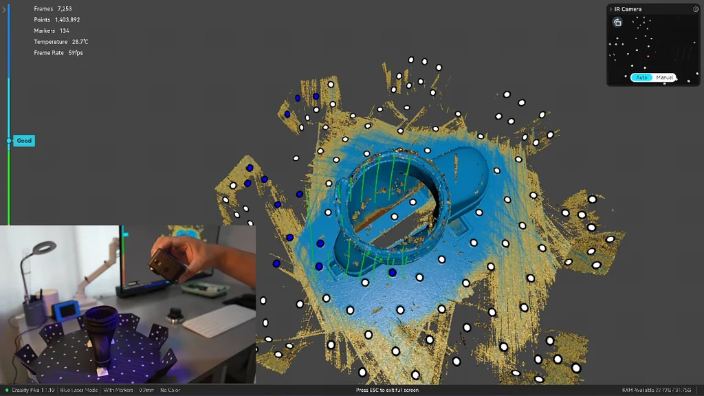
Moving to the Pika scanner, I noticed the seven-line capture range is smaller than the X1. It behaves more like the Raptor series. Even with fewer markers detected, the Pika tracks the inlet taper on the turntable surprisingly well. The depth perception is solid. Tracking isn't as strong as the X1, but it remains functional.
Post-Processing Scan Data
Post-processing starts with the plane clipping function in Creality Scan. By picking three points on the pyramid support, I can isolate the part from the turntable. I then use single-body selection to invert and remove the remaining noise. For point cloud fusion, I set the resolution to 0.2 mm while keeping noise removal at the 40% default setting. After fusion, the next phase is aligning the two sides of the scan data. It's a clean process.
Comparing Mesh Results
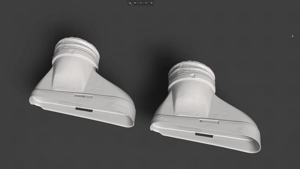
Comparing the X1 and Pika meshes, both result in roughly 5 million faces. On closer inspection, the Pika surface is noticeably rougher, indicating lower precision. The X1 captures inner walls more effectively, whereas the Pika leaves some blind spots. I import the X1 point cloud into CloudCompare, switch to a green display, and enable EDL visualization. Aligning the flat surface to the XY plane is the next logical step.
Evaluating Point Cloud Quality
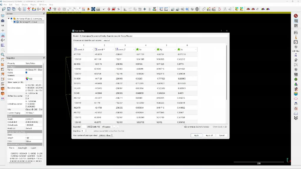
I bring in the Pika scan data to compare against the X1. The Pika data is displayed in yellow for contrast. Looking at the cross-section, the wall line is less consistent and lacks the sharpness of the X1 scan. While the difference is minor here, it becomes pronounced on metal components like a gauge block. I'll align the Pika cloud over the X1 for a final dimensional check.
Setting Up BricsCAD for Reverse Engineering
I'm using BricsCAD for this reverse engineering tutorial. It's a powerful tool for this work. I create two new layers: one for sketches and one for the final solid model. The interface might look different from your version, but the commands are standard. I've provided a point cloud download link to help you follow along. It's a great way to learn.
Defining the Sketch Plane
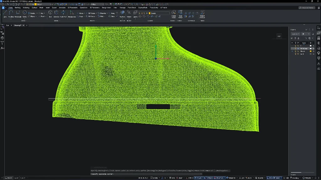
First, change the viewport to the top view. By default, the origin is at the world UCS, so I move it to the flat area of the part. I use the 3D E-snap (F4) to snap the UCS origin directly onto the point cloud. Now the sketch plane is correctly positioned. Before tracing, turn off 3D E-snap. It's cleaner that way.
Creating Tangent Sketches
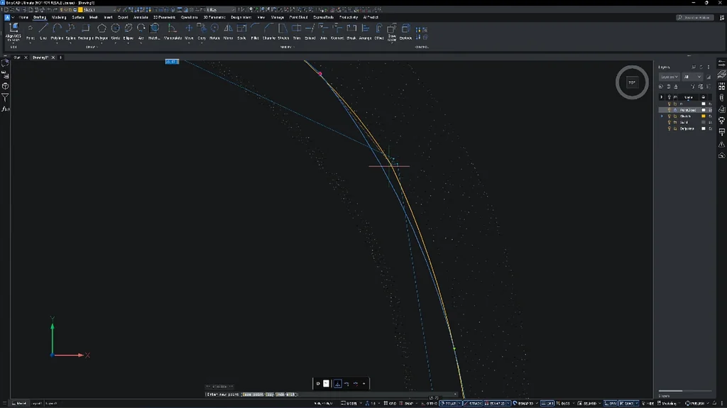
Tracing with polylines is the fastest approach for smooth sketches here. Create the segment, then use the 'add bulge' command to slide the vertex until it's tangent. It's a solid workflow. Always save your data in the native DWG format. Orbit the viewport until you can see the top ring of the intake, then crop the point cloud to isolate that section.
Building the Profile Guide Rails
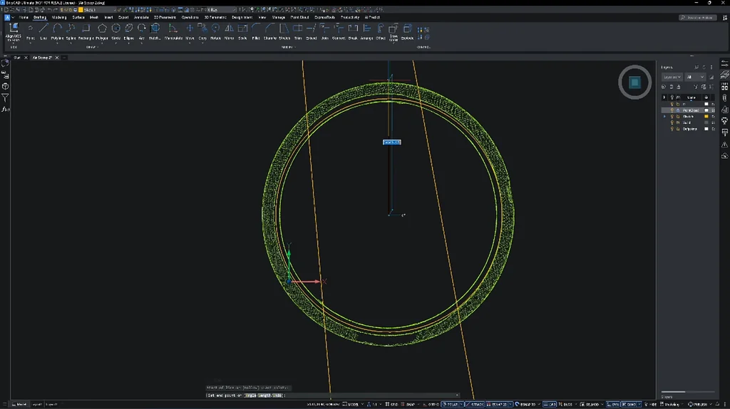
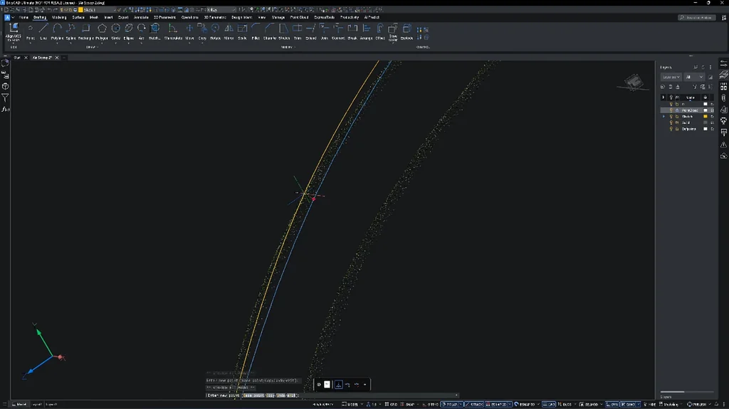
Extend the circle center to maintain alignment. If S-track is on, you can drag the vertex to adjust. I use the center line as a guide and apply the move command to keep the circle centered. It's simple. We need guide rails to ensure the lofted surface fits correctly. Create a straight line between the two sketches and move the UCS plane to match.
Adjusting Guide Rail Direction
Rotating the UCS axis shifts the X and Y axes, which controls the guideline direction in polar tracking. You need another guide rail on the opposite side. Create a line between the two sketches and move the UCS plane. Use a spline to snap along the line, then hide it to reveal the underlying geometry. It's precise work.
Executing the Loft Command
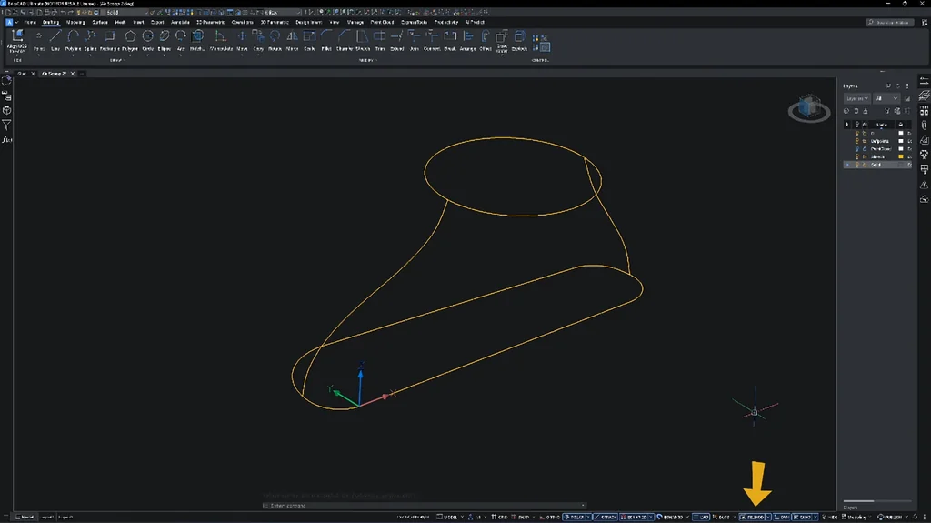
Turn on selection mode and hover over the sketch to detect the boundary. Choose 'create region' from the quad menu. Use the UCS entity command to move the UCS to the top sketch profile. Hover again to create the second region. The cross-sectional area represents half the capsule, where pressure builds up. Click 'loft' and select both regions to generate the surface.
Refining Surface Smoothness
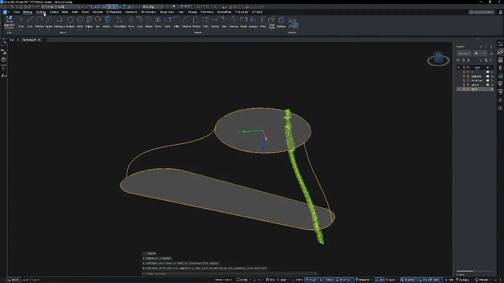
If the lofted surface has a dimple, you need extra guide rails. Create a line between the sketches, uncrop the point cloud, and isolate the problematic portion. Use the UCS axis between the two sketches to trace a spline along the line. It's necessary for a smooth finish. This ensures the airflow remains laminar.
Extruding and Trimming Surfaces
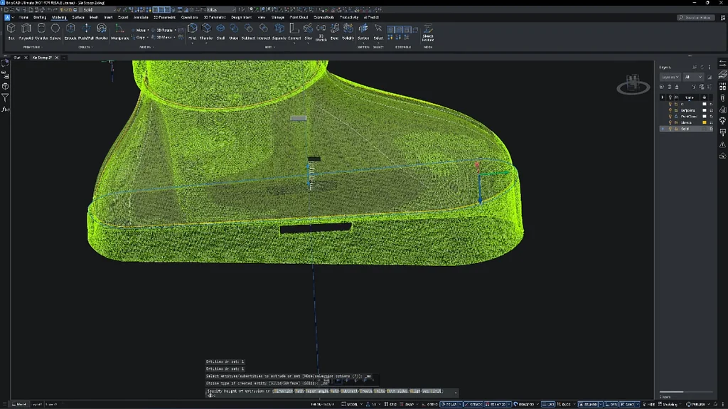
Select the offset profiles and use the extrude command to pull them to the required length. Rotate the UCS by 90 degrees and trace a line for trimming. On the surface tab, click 'extrude surface' and type 'B' to extrude on both sides. Use the slice command to trim the solid. It's a clean cut. Delete the excess cutting surface afterward.
Applying the Shell Command
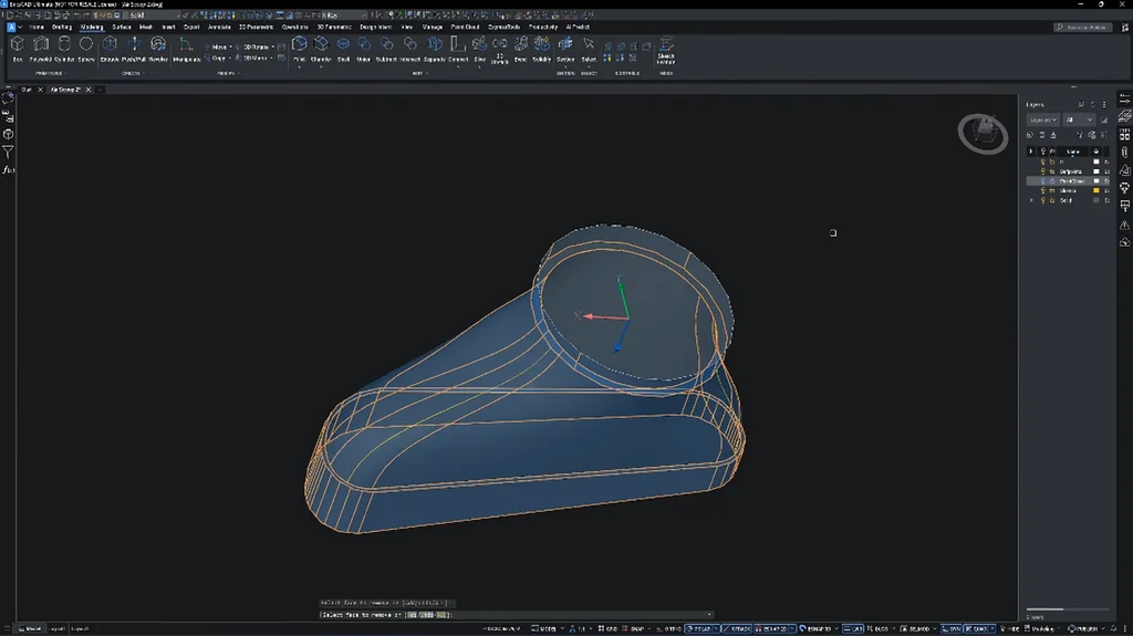
Select the top and bottom faces and apply a 2.6 mm shell thickness. The original part was 1.9 mm, but that's too thin for printing. If you need to resize the ring, use the push-pull command. It's very flexible. Use the extract command on the edge to get a circle, offset it by 5 mm, and extrude it to form the backing.
Finalizing Geometry and Cutting
Extrude the circle inward by 2 mm and then downward. Hit the control key twice to enter cutting mode. Use the section view command to create a section and back it off by a few millimeters. Trim any un-smooth cuts that might cause turbulence. It's solid. Make sure your selection mode is active.
Trimming Locking Slots
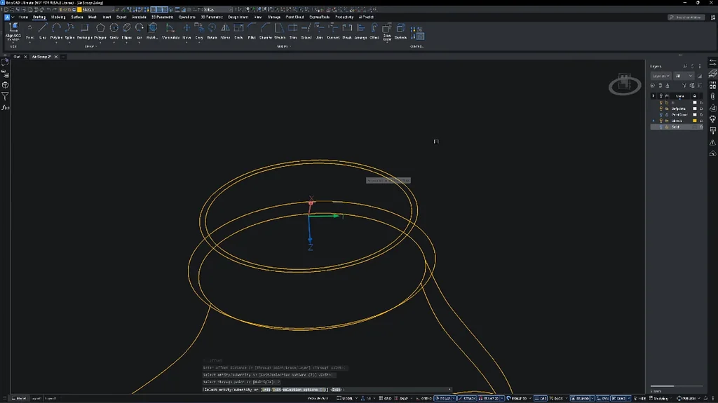
Almost there. Move the UCS origin to the desired location and switch to the top view. Toggle off the solid layer and create a polyline for trimming. Use 'extrude surface' on both sides and then the slice command to clean up the solid. Remove the cutting surface once done. There are two more slots for locking. It's ready.
Exporting for 3D Printing
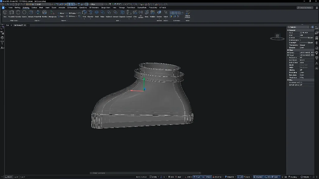
Type 'STL out' in the command line and select 'High' for settings. If you have the communicator package, export as a STEP file. Drag and drop the STEP file into Orca Slicer. It converts the file into a mesh for printing. It's straightforward. Find the proper orientation and add supports.
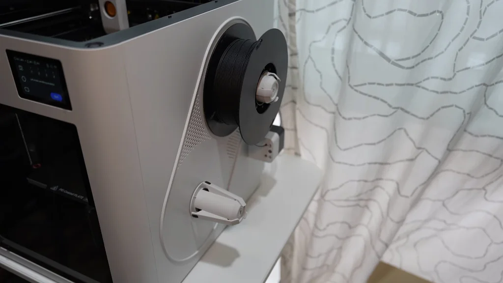
Printing with the Snapmaker U1
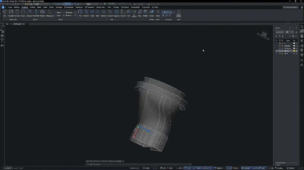
When your filament is dry, support removal is easy. I don't use different materials for support interfaces anymore. This applies to both ABS and ASA. I'll test the fit with the existing air hose. The original used adhesive, but since this new part is a different size, I'll send the STEP file to the customer. He can adjust it himself.
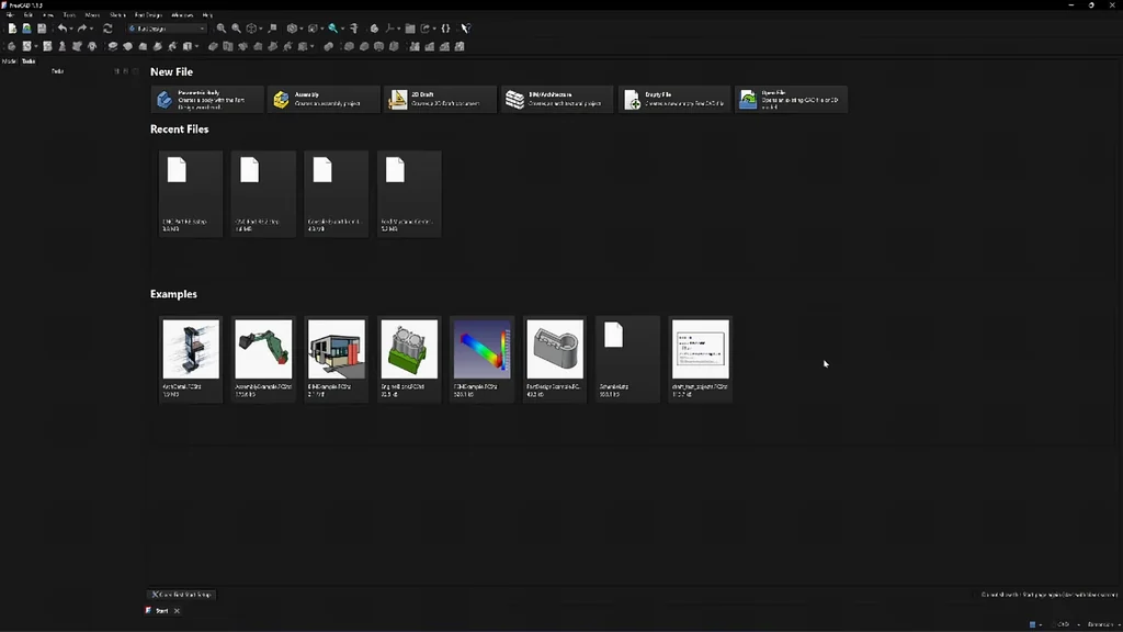
Opening STEP Files in FreeCAD
A STEP file is a CAD file, not a mesh. That means you can't open it in standard mesh software. In FreeCAD, it opens as if it were modeled directly. There are no mesh faces. You can't perform additive or subtractive extrusion on it, but the customer can still modify the mounting face. The print feels stiffer than the original. It's solid.
⚠️ CAUTION: SAFETY WARNING!
Always wear eye protection when using 3D printers and handling support removal tools. Ensure your workspace has proper ventilation when printing with ABS or ASA to avoid inhaling fumes.
Summary & Tips
Reverse engineering allows you to replace obsolete or poorly designed car parts with custom, high-quality alternatives. Using the right scanning and CAD workflow ensures the new component fits perfectly. The transition from a felt-based intake to a rigid 3D-printed part significantly improves airflow and longevity. This process is a practical skill for any workshop enthusiast.
📋 FAQ
❓ Can I use PLA for car intake parts?
No, don't do that. PLA will warp under the high temperatures found in an engine bay. Use ABS or ASA instead.
❓ Is BricsCAD hard to learn?
Honestly, it's quite intuitive if you have experience with CAD. The commands are very similar to other industry-standard software.
❓ Do I need a high-end scanner?
Depends on your requirements. If you need extreme precision, yes, but for basic intake ducts, mid-range scanners work fine.
❓ Why use STEP files instead of STL?
Usually, STEP files contain precise geometric data. STL files are just meshes, which makes them much harder to modify later.
Disclaimer: I purchased all tools for this guide with my own money to ensure an unbiased review. This post contains affiliate links, meaning I earn a small commission if you make a purchase at no extra cost to you.