Power stations like the Pecron E3600LFP are built to handle heavy loads, yet the inverter protection circuitry inside them can still give out after extended use. This repair manual covers the full disassembly sequence needed to reach that faulty module, swap it for a working one, and button everything back up securely. Since the interior of this machine is densely packed, you’ll want a quality set of precision drivers and plenty of patience to maneuver through the wiring without tearing anything.
⚡ Quick Guide: How to Make It in 10 Steps
- Loosen the top cover screws and lift off the outer shell.
- Unplug the harnesses and ribbon connectors from the mainboard.
- Spot the protection module responsible for inverter safety.
- Disconnect and extract the damaged board from its housing.
- Check adjacent components for scorching or swollen caps.
- Seat the replacement module and lock every plug into place.
- Route the wires neatly so nothing gets crushed or shorted.
- Tighten the chassis bolts manually with a screwdriver.
- Finish the exterior shell using a drill on low clutch.
- Power on the station and confirm the inverter kicks in.
📋 In This Article
- Technical Specifications & Components
- Tools & Materials Used — what you will need for this project
- Removing the Top Chassis Panel
- Accessing Internal Components
- Inspecting the Power Station Internals
- Top-Down View and Component Mapping
- Removing the Faulty Protection Board
- Analyzing Internal Wiring and PCB Layouts
- Securing the New Protection Board
- Using the Electric Drill for Reassembly
- Verifying Connections and Ports
- Final Panel Securing
- FAQ
📊 Technical Specifications & Components
| Device | Pecron E3600LFP |
| Component | Inverter Protection Board |
| Chassis Type | Portable Power Station |
| Fastener Type | Phillips Head Machine Screws |
| Internal Connectivity | Multi-pin Ribbon Cables |
| Cooling System | Integrated Forced Air |
📊 Project Overview & Costs
🔧 Difficulty Level: Hard
⏱️ Time Investment: DIY: 2-3 hours | Pro: 60-90 minutes
💰 Professional Service Cost: $150-$250
💡 Verdict: Handling this repair yourself skips the freight charges and bench fees that come with shipping a bulky battery unit across the country.
🛠️ Tools & Materials Used
• Precision Tweezers
• Anti-Static Mat
• Plastic Spudger
Step-by-Step Assembly & Testing
Removing the Top Chassis Panel
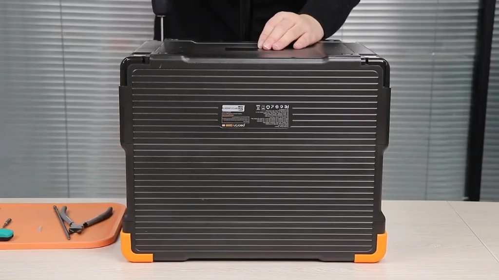
Before touching anything, clear off your workbench so the hefty E3600LFP has room to sit without you fighting for elbow space. The first mechanical task is backing out the screws along the perimeter of the top cover. These tend to be snug from the factory, so pick a driver that seats perfectly in the cross pattern to avoid camming out. Drop the fasteners into a small dish or magnet tray so nothing rolls off the table. When the last one is free, lift the lid vertically instead of tilting it—there could be a wire harness resting right underneath.
Accessing Internal Components
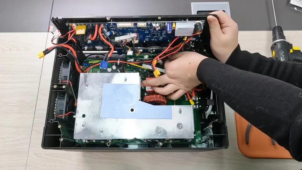
Now that the shell is off, the real estate inside is immediately overwhelming. Before disconnecting anything, map out where the thick power leads and thin signal cables run. This mental snapshot helps later. The connectors here almost always feature a locking tab on one side—squeeze it while pulling straight back on the plug. Never yank on the wires themselves. A nylon spudger works wonders for popping stubborn connectors loose without cracking the plastic housings.
Inspecting the Power Station Internals
Focus now on identifying the protection board among the cluster of PCBs. This particular module handles the critical job of watching inverter output and shutting things down if limits are exceeded. Look carefully. Telltale signs of trouble include capacitors that have domed tops, a brownish discoloration on the solder mask, or components that simply look cooked. Photograph any damage you find for documentation. Blasting the area with some canned air is also a smart move to get rid of accumulated dust before you dig deeper.
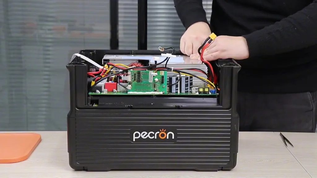
Top-Down View and Component Mapping
Looking straight down at the chassis reveals how the protection board sits relative to the inverter stack. Make sure nothing blocks your access to the mounting hardware. There isn't much wiggle room. Shift the cables aside without pulling them taut—putting tension on a solder joint is asking for trouble. When a wire won't cooperate, follow it to the nearest zip tie and cut that restraint instead. A clear path is non-negotiable.
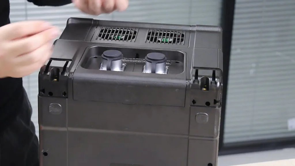
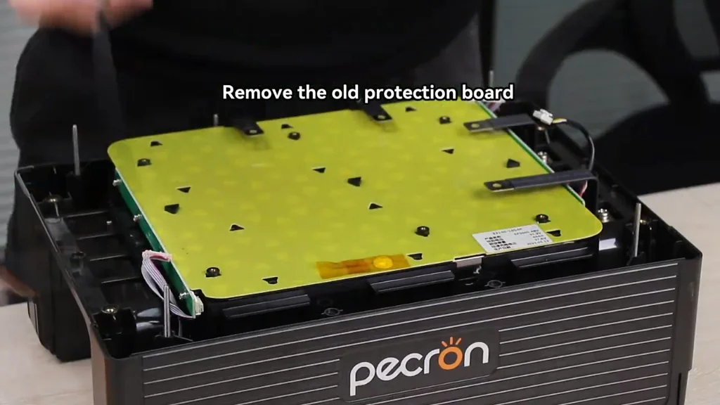
Removing the Faulty Protection Board
Proceed by loosening the screws that anchor the protection module to the standoffs. The clearance is minimal, and these tiny screws will disappear into the battery bay if you fumble them. Use tweezers or a magnetic tip. After the hardware is out, lift the board straight upward so the header pins disengage cleanly. If it refuses to budge, scan for a hidden screw or a dab of adhesive holding the corner down. Place the old board beside the replacement to verify they match up.
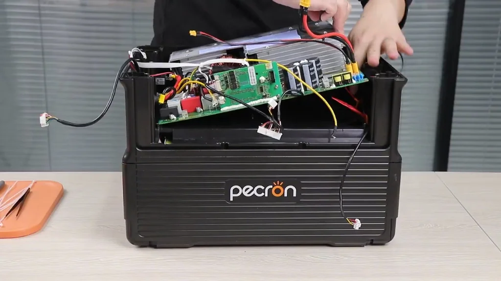
Analyzing Internal Wiring and PCB Layouts
Spend a moment examining the bundle of wires that connects to the protection board. Each plug is shaped differently, but noting which color wire goes where provides an extra layer of insurance. This step matters. Reversing a signal line during reassembly would be a costly mistake. If your memory isn't perfect, stick a small piece of tape on each connector and label it. That way, you won't hesitate when it's time to plug everything back in.
Securing the New Protection Board
Lower the new module onto the standoffs and line up the mounting holes precisely. Turn each screw counterclockwise first until you feel a click—this helps seat the threads properly. Then drive them in clockwise. The resistance should be even. Stop as soon as the screw head touches the board; any further tightening risks cracking the laminate or stripping the brass inserts. Hand tools give you the control needed to feel that stopping point.
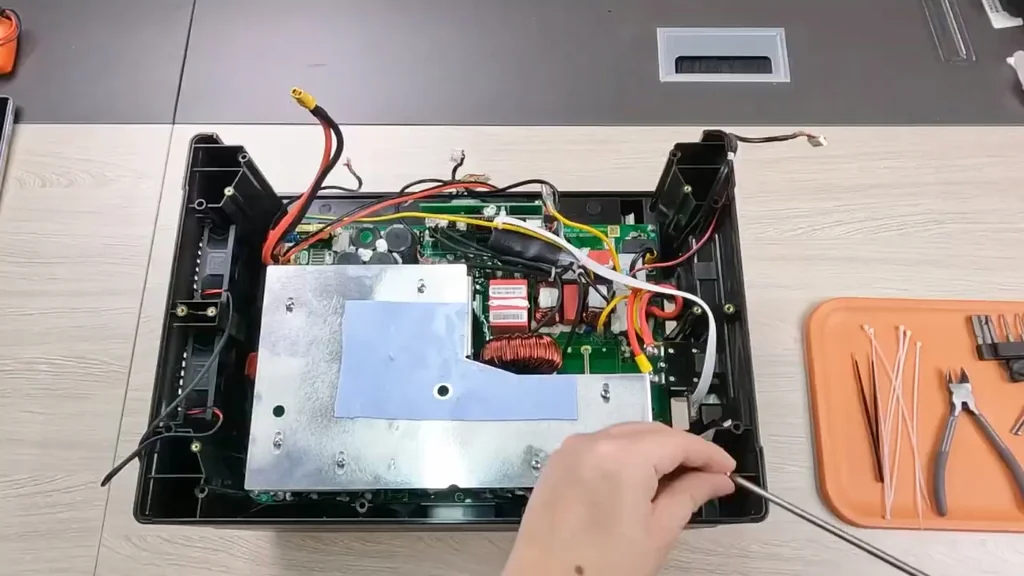
Using the Electric Drill for Reassembly
An electric drill can cut your reassembly time in half, but only for the outer case. Dial the clutch all the way down. If you leave it on full power, the plastic threads will strip out in a heartbeat. Reserve the drill for the big structural bolts that hold the shell together. For anything mounted to a circuit board, keep using your manual screwdriver—that extra bit of tactile feedback prevents disaster.
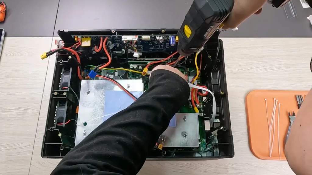
Verifying Connections and Ports
Before you seal the enclosure, revisit every connector you handled during the repair. Press firmly on each one until the locking tab clicks into its seated position. Skipping this check is asking for trouble. A half-seated ribbon cable can cause the inverter to throw an error code the moment you power up. Also, peer into the external ports to make sure no stray screws or plastic bits have wandered inside. The unit should look as clean as it did from the factory.
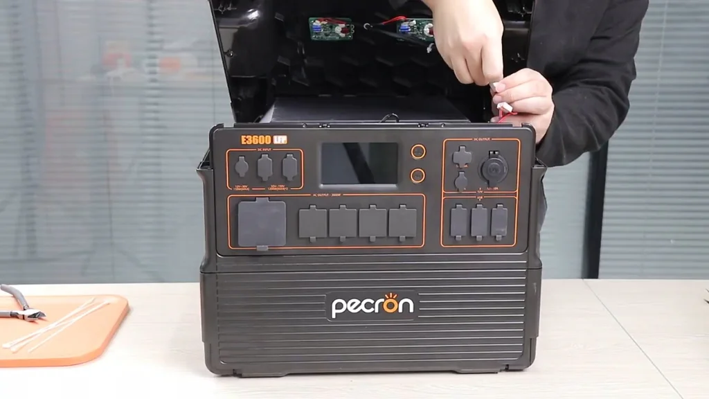
Final Panel Securing
Set the top panel back onto the chassis, making sure the gasket sits flat and no wiring is trapped along the seam. The finish line is close. Run the outer screws in with the drill on its gentlest setting, alternating sides so the panel seats evenly. When everything is snug, lift the station an inch off the bench and give it a light shake. No rattles means you're good to go. Power it up and verify the inverter outputs clean AC.
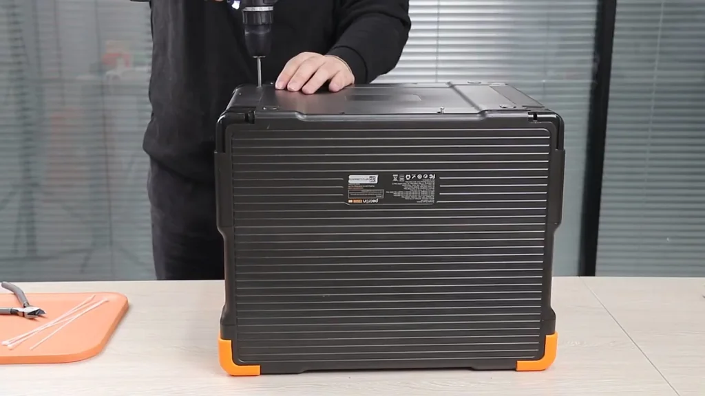
⚠️ CAUTION: SAFETY WARNING!
Make certain the large capacitors are fully discharged before your fingers get near any exposed contacts to prevent a serious electrical shock. Protective eyewear is also worth wearing in case a small part goes flying while you're prying things apart.
Summary & Tips
Swapping out the protection board on an E3600LFP is a job that demands a methodical approach and a spotless workspace for organizing screws. Keep track of the cable routing, double-check every connection, and you'll have this unit running again without a trip to the service center. A careful final inspection before powering up is the key to avoiding expensive mistakes. This repair is absolutely doable for anyone with steady hands and the right tools.
📋 FAQ
❓ Is it safe to open the Pecron E3600LFP?
For the most part, yes—provided you discharge the capacitors and avoid touching live terminals. Take your time and it's manageable.
❓ Can I use a standard drill for all screws?
That's a bad idea. A standard drill puts out too much torque for the small PCB fasteners. Keep it manual for internals and use the drill only on the outer shell.
❓ What if a ribbon cable is damaged?
You'll need to order a replacement from the OEM. Fixing high-density ribbon cables at home is rarely successful. It's a straight swap.
❓ How do I know if the protection board is the problem?
The classic symptoms are an error code on the display or zero AC output despite a full battery. A visual inspection showing burned traces or blown components confirms the diagnosis.
Disclaimer: I purchased all tools for this guide with my own money to ensure an unbiased review. This post contains affiliate links, meaning I earn a small commission if you make a purchase at no extra cost to you.