Traditional FDM 3D printing often results in parts that snap easily along layer lines because the filament is deposited cold and fails to properly fuse with the preceding layer. By integrating a laser diode directly onto the print head, you can pre-melt the material at the point of contact. This setup significantly improves Z-axis tensile strength, allowing for structural parts that perform closer to their XY-plane counterparts without needing a heated chamber.
⚡ Quick Guide: How to Make It in 5-10 Steps
📋 In This Article
- Technical Specifications & Components
- Tools & Materials Used — what you will need for this project
- Understanding FDM Layer Weakness
- Analyzing the Critical Bond Area
- Implementing Laser-Assisted Fusion
- Testing Material Strength Results
- Evaluating Laser Power Efficiency
- Analyzing Cooling Variable Effects
- Comparing Black PLA Cooling Curves
- Testing Wall vs Infill Printing
- Optimizing Laser Pathing
- Experimenting with Annealing Techniques
- Reviewing Laser Power Levels
- Investigating Physical Print Failures
- Identifying Mechanical Weak Points
- Assessing Visual Laser Marks
- Finalizing the Open Source Release
- FAQ
📊 Technical Specifications & Components
| Printer Model | Neptune 4 |
| Laser Configuration | Dual diode setup |
| Material Compatibility | PLA, Carbon Fiber PLA, ABS |
| Strength Improvement (PLA) | Up to 60% |
| Strength Improvement (ABS) | Up to 40-80% |
| Optimal Cooling (PLA) | 20% fan speed |
| Optimal Cooling (CF) | (PLA): 40% fan speed |
| Laser Power (Wall Printing) | 15-25% duty cycle |
| Maximum Achieved Strength | 94% of XY baseline |
📊 Project Overview & Costs
🔧 Difficulty Level: Hard
⏱️ Time Investment: DIY: 12-16 hours | Pro: 6-8 hours
💰 Professional Service Cost: $150-$300 in components
💡 Verdict: Eliminates the need for expensive high-temperature enclosures while drastically increasing part reliability.
🛠️ Tools & Materials Used
• Laser Diode Module
• PLA and ABS Filament
• Carbon Fiber Reinforced PLA
Step-by-Step Assembly, Testing & Inspection
Understanding FDM Layer Weakness
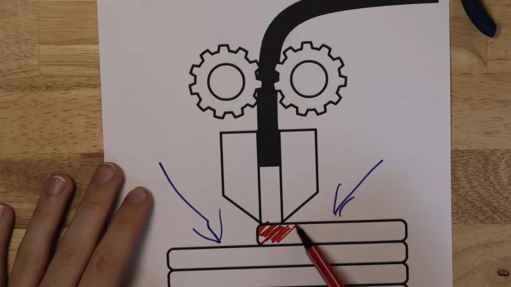
Standard FDM printing is inherently flawed. You are depositing hot plastic onto a cold surface. The material doesn't fuse properly. It just sits there. This creates a weak mechanical bond. The layers are basically stacked like a pile of bricks. They aren't chemically bonded. This is why parts snap along the Z-axis so easily.
Analyzing the Critical Bond Area
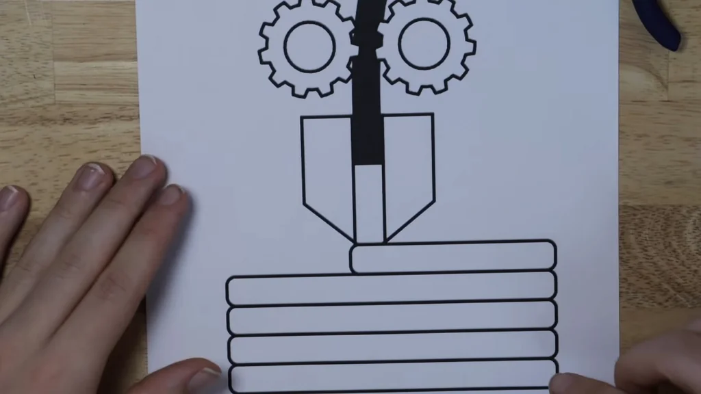
When the nozzle deposits filament, it only heats the immediate area to around 200°C. That's not enough to melt the layer below. The heat transfer is minimal. The bond area is tiny. It's really weak. We need to introduce external heat. That's the only way to fix it.
Implementing Laser-Assisted Fusion
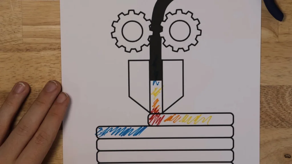
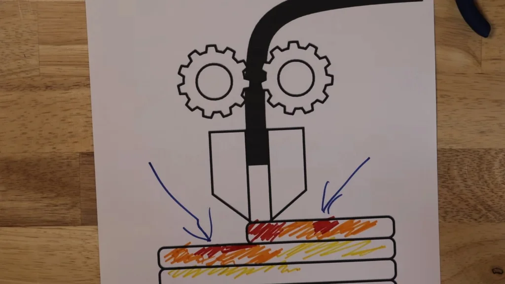
We mount a laser diode to the nozzle. It creates a hot spot right where the filament lands. This changes the temperature gradient entirely. Now the surface below is pre-heated. The bond is much stronger. It moves with the nozzle. The heat is applied exactly where needed.
Testing Material Strength Results
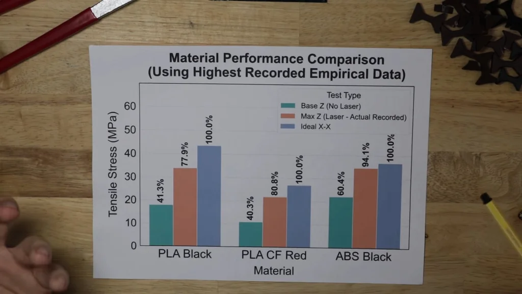
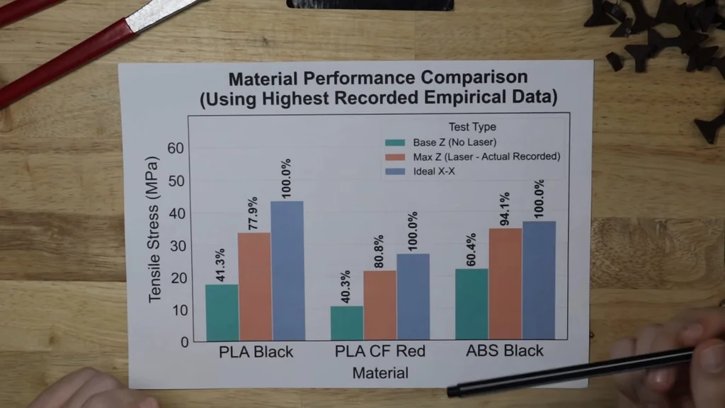
I tested black PLA, red carbon fiber PLA, and generic black ABS. The results were clear. We compared Z-axis strength against the ideal XY-axis strength. The difference is massive. It's a huge gap. My generic AliExpress filament wasn't even high-grade. Still, the improvement was significant. We saw a 60% increase for PLA. That's a huge jump. It changes everything.
Evaluating Laser Power Efficiency
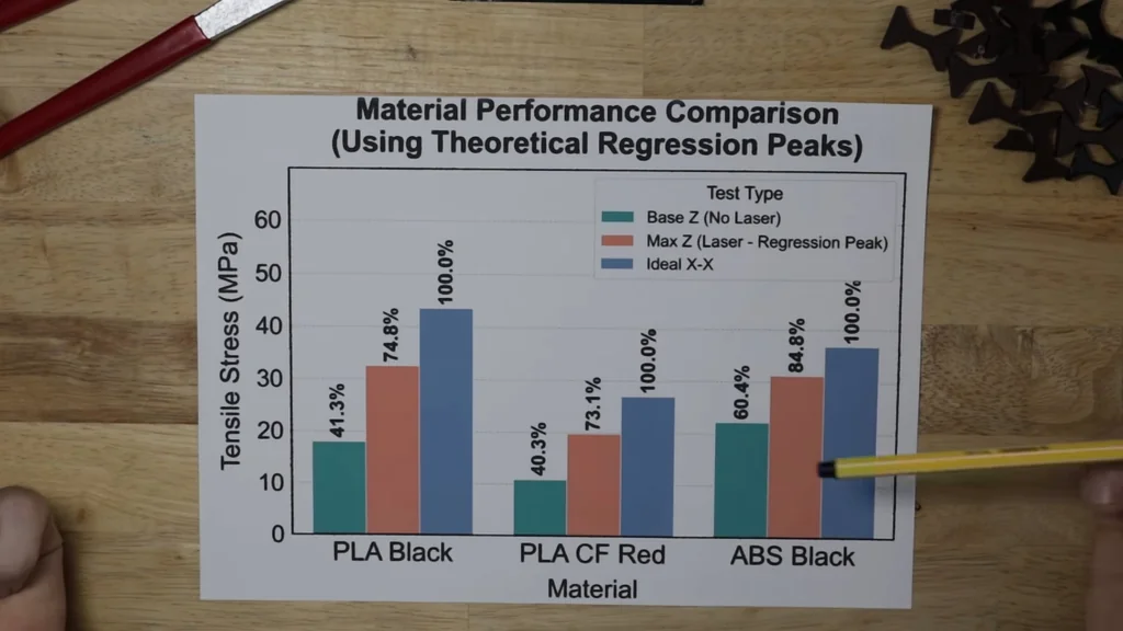
Adding laser power closes the gap. For ABS, we achieved 94% of the ideal strength. That's impressive. These were the highest recorded values. I cherry-picked the best results. The statistical model confirms the trend. It's a solid improvement.
Analyzing Cooling Variable Effects
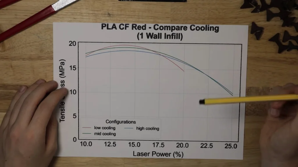
Cooling is a major variable. I tested different fan speeds. For red carbon fiber PLA, lower cooling is better. 40% fan speed worked best. It beat the 60% and 80% settings. The technique works. It's consistent.
Comparing Black PLA Cooling Curves
Black PLA showed similar behavior. 20% cooling was the winner. The higher cooling settings performed worse. It's below the baseline. The curves look different, though. It's a complex variable.
Testing Wall vs Infill Printing
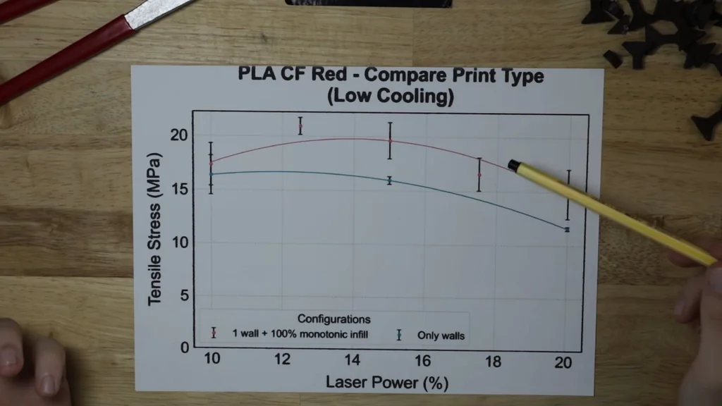
I compared one-wall prints with 100% monotonic infill. The results were lower for carbon fiber PLA. Same for ABS. Why? It's a machine limitation. The Y-axis extrusion is the bottleneck. The nozzle path matters.
Optimizing Laser Pathing
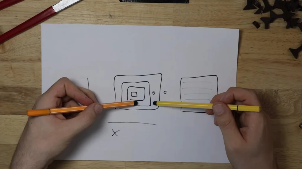
The laser spots are always next to the nozzle. If we go parallel to the Y-axis, we miss the mark. We shoot next to the line. That's not what we want. My workaround is using half power. It's inconsistent but functional. Four lasers would be optimal.

Experimenting with Annealing Techniques
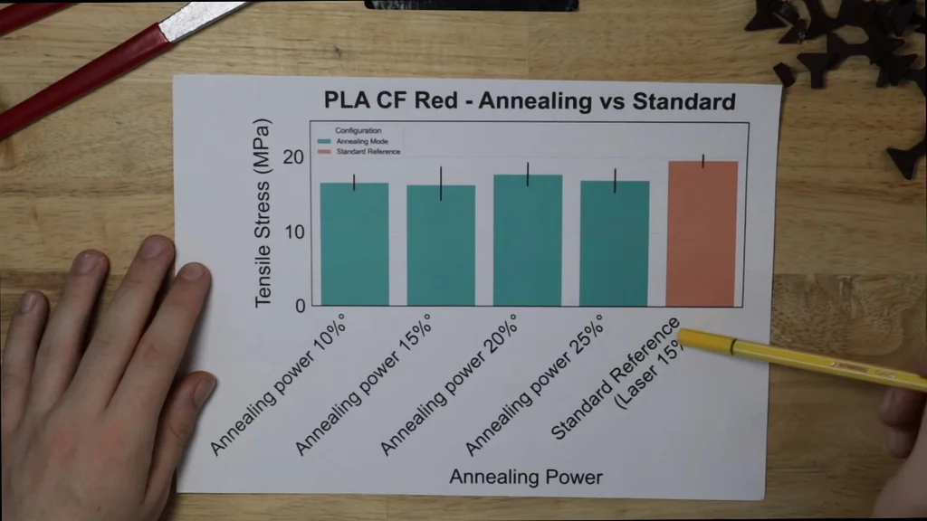
I tried annealing during the print. I went over the layer again with the laser. It didn't help. The results were non-existent. It's not a benefit. I also tried brick layers. I couldn't get them working. It caused air gaps. The G-code was problematic.
Reviewing Laser Power Levels
I tested 10% to 25% laser power. The difference was non-existent. It's smaller than the reference. It doesn't benefit. I need to figure out why brick layers fail. It's a good try. Maybe it's the G-code.
Investigating Physical Print Failures
I'm still investigating the brick layer issue. They are weaker. It's frustrating. I'm looking at the max strength data again. The gaps are trendy. The carbon fiber filament wasn't optimized. The ABS is better.
Identifying Mechanical Weak Points
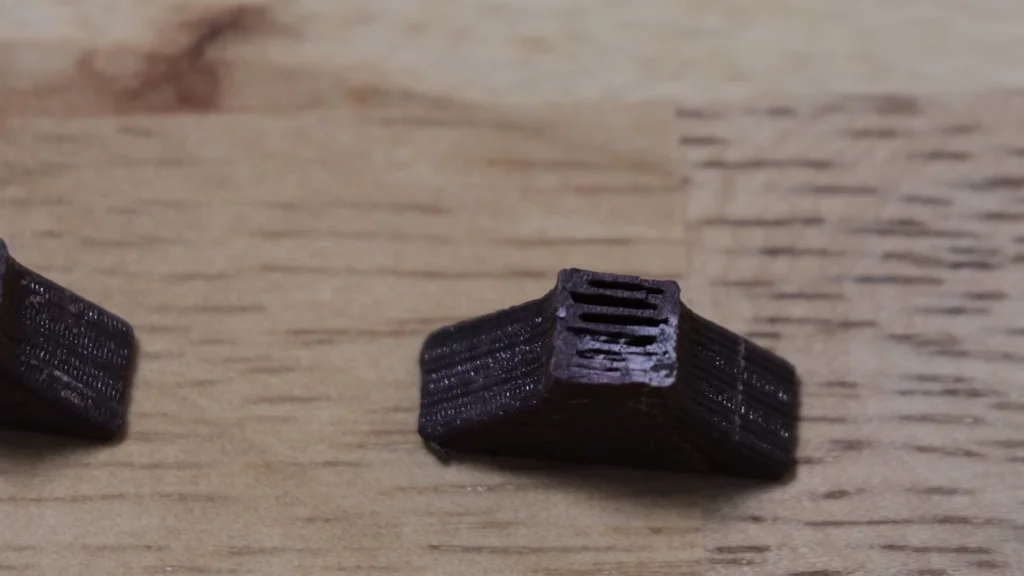
The problem isn't the strength itself. It's the layers. We have small gaps. These are inherently weak points. The area is smaller there. That's the issue. We get mechanical failure. We can eliminate the air gaps.
Assessing Visual Laser Marks
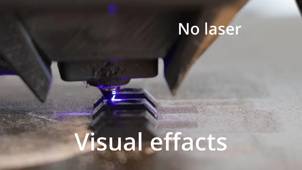
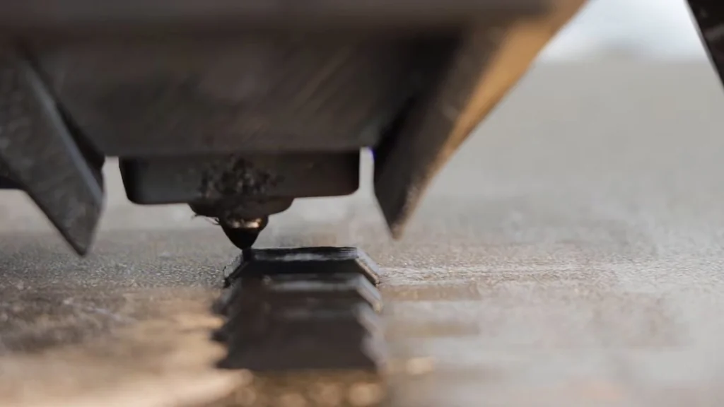
Do they look different? Not really. The optimal samples have visible laser marks. They go vertically down. They are visible. They aren't relevant to the part function. The parts are layered. It's a vertical layer effect.
Finalizing the Open Source Release
I'm planning to release the files. If there is enough interest, I'll open source the build. Everyone can do their own testing. It's a community effort. Let's make additive manufacturing stronger. See you in the next few weeks.
⚠️ CAUTION: SAFETY WARNING!
Laser radiation is dangerous to eyes; always wear appropriate safety goggles and never look directly at the beam. Ensure the laser mount is secure to prevent accidental firing at non-print surfaces.
Summary & Tips
Laser-assisted fusion is a viable path toward isotropic 3D printed parts. While the setup requires custom calibration and G-code adjustments, the strength gains are undeniable. This approach effectively bridges the gap between hobbyist FDM and industrial-grade additive manufacturing. Future iterations will focus on refining the laser pathing to eliminate inconsistencies.
📋 FAQ
❓ Does this work with all filament types?
Honestly, it depends on the material's thermal properties. I've only tested PLA and ABS so far. Different materials will require different laser power settings.
❓ Is a heated chamber still required?
No, that's the point of this project. The laser provides the necessary heat locally. You don't need a full enclosure anymore.
❓ How hard is the installation?
It's a complex build. You need to mount the diode and manage the wiring. It's not for beginners.
❓ Will you release the files?
Yes, I'm cleaning up the CAD now. I'll release everything as open source soon. Keep an eye out for the update.
Disclaimer: I purchased all tools for this guide with my own money to ensure an unbiased review. This post contains affiliate links, meaning I earn a small commission if you make a purchase at no extra cost to you.