960Wh of LiFePO4 capacity packed into a unit costing only $309 — that’s what I found when I cracked open the new EcoFlow Delta 3 1000 Air. I wanted to see exactly how they managed to hit that price point while maintaining a 500W continuous inverter. I pulled the casing apart to inspect the internal components, battery architecture, and overall build quality of this latest addition to the Delta lineup.
⚡ Quick Guide: How to Make It in 15 Steps
- Removed 5 screws from the exterior housing to access the internal components.
- Disconnected the modular display communications cable to separate the front panel.
- Identified the AC input fuse, relay, and cooling fan rated at 12V 300mA.
- Measured 9V at the main battery terminals, indicating a low-voltage state or BMS lockout.
- Removed 10 perimeter screws to lift the main inverter board for inspection.
- Confirmed the use of aluminum case prismatic cells within the battery pack.
- Located two temperature sensors affixed near the negative battery terminal.
- Inspected the stainless steel bands and foam padding securing the battery cells.
📋 In This Article
- Technical Specifications & Components
- Tools & Materials Used — what you will need for this project
- Removing the Exterior Housing
- Inspecting the Main Board Components
- Tracing the DC Charging Circuit
- Disconnecting the Inverter Board
- Analyzing the Circuit Board Coating
- Evaluating BMS Functionality on the Board
- Investigating Transistor Arrays
- Checking Relays and Front Panel
- Examining Communications Pins
- Accessing the Battery Pack
- Identifying Temperature Sensors
- Checking Bus Bar Construction
- Inspecting Cell Insulation
- Evaluating Cell Brand Quality
- Final Assessment of the Unit
- FAQ
📊 Technical Specifications & Components
| Battery Chemistry | LiFePO4 |
| Total Capacity | 960Wh |
| Inverter Rating | 500W Continuous |
| Cooling Fan | 12V 300mA |
| Battery Configuration | 3-cell series |
| Nominal Voltage | 9.6V |
| Cell Type | Aluminum case prismatic |
📊 Project Overview & Costs
🔧 Difficulty Level: Medium
⏱️ Time Investment: DIY: 45 minutes | Pro: 20 minutes
💰 Professional Service Cost: $0
💡 Verdict: I saved the cost of a replacement unit by performing my own diagnostic inspection.
🛠️ Tools & Materials Used
• Plastic pry tools
Tearing Down the EcoFlow Delta 3 1000 Air
Removing the Exterior Housing
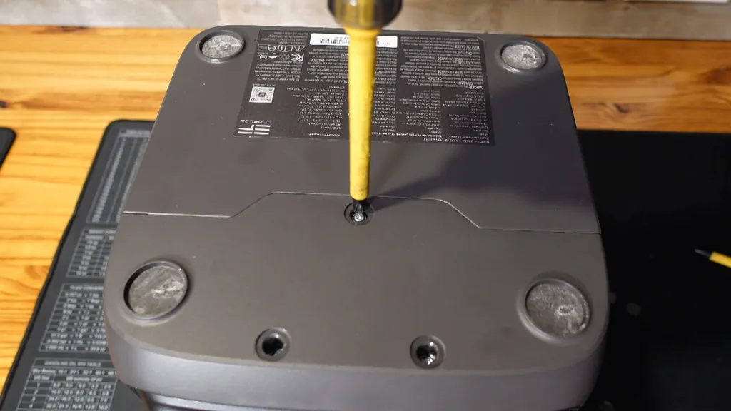
I started by locating the fasteners on the exterior of the power station. I removed three Phillips screws from the rear section and two more from the lower front area. I spotted two distinct pry marks on the lower front side, which helped me carefully separate the shell. Once the casing loosened, I disconnected the modular communications cable that links the display to the main board.
Inspecting the Main Board Components
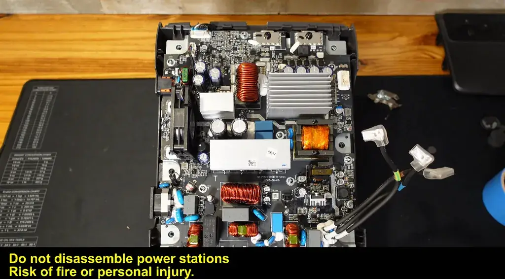
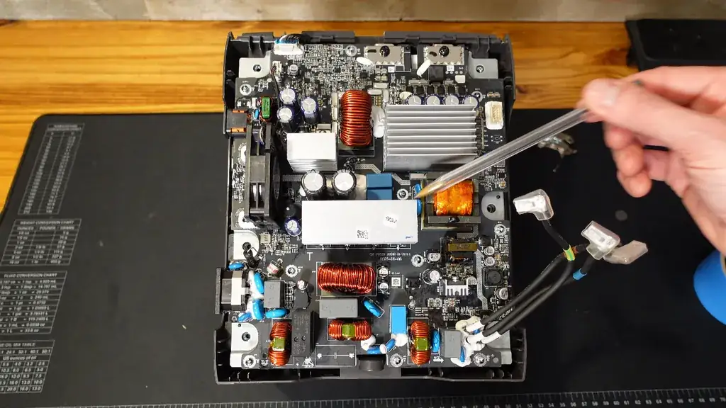
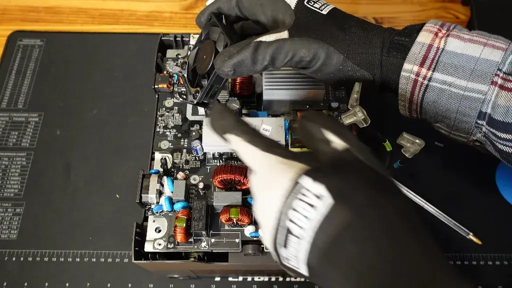
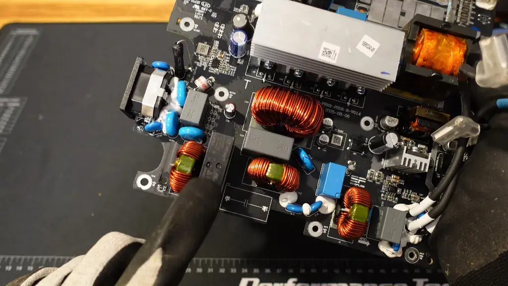
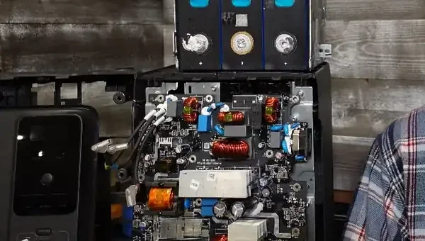
I examined the main board to identify the power management layout. I found a fuse protecting the AC input, followed by a relay that handles the transfer between grid power and the inverter. I noted several large inductors, a transformer, and a bank of FET transistors. The cooling fan I pulled from the assembly is a 12V 300mA unit, which felt light in my hands.
Tracing the DC Charging Circuit
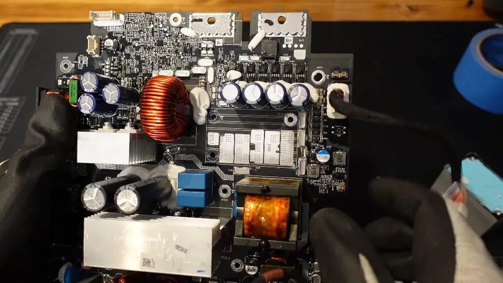
I focused on the upper left section of the board, which manages the DC input. This is where the solar panel or DC charger connects. I identified the capacitors and the large inductor dedicated to the charging circuit. The two primary terminals at the top of the board serve as the B- and B+ connections for the battery pack.
Disconnecting the Inverter Board
I measured only 9V at the main battery terminals, so I suspected the BMS might be in a lockout state or the battery voltage was simply very low. I disconnected the communications lead and the battery terminals to clear the path. I then removed 10 Phillips screws around the perimeter of the inverter board, plus a few in the center, to lift it away from the chassis.
Analyzing the Circuit Board Coating
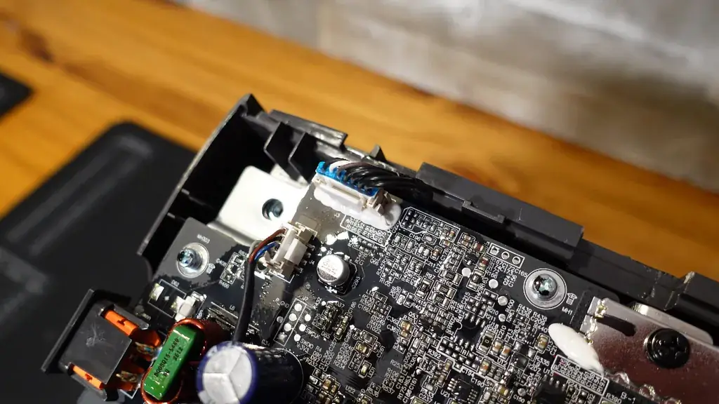
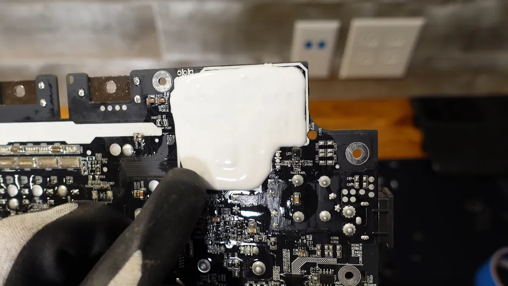
I took a closer look at the circuit board once it was free. I noticed that most of the board features a conformal coating, though it didn't look like a total encapsulation. The bottom side also had this protective layer. I was interested to see the high number of conductors running from the battery to the communications cable.
Evaluating BMS Functionality on the Board
I spotted several FETs and large resistors that appeared to be shunt resistors for current sensing. I wondered if EcoFlow integrated the BMS functionality directly into the main inverter board to save on manufacturing costs. This would be a departure from the separate BMS boards I usually see in these units.
Investigating Transistor Arrays
I looked at the series of FET transistors located directly underneath the main control section. I'm not entirely certain if these are dedicated to the charging circuit or the BMS control. I suspect they are for the BMS, but I'd be interested to hear if anyone has a definitive answer on this specific board layout.
Checking Relays and Front Panel
I examined the relays, noting one that appears to switch both the line and neutral on the input. I also found a blue relay, which I believe handles the output switching. I checked the back of the front panel, where a ribbon cable connects the display to the main board, and I saw the USB-A ports.
Examining Communications Pins
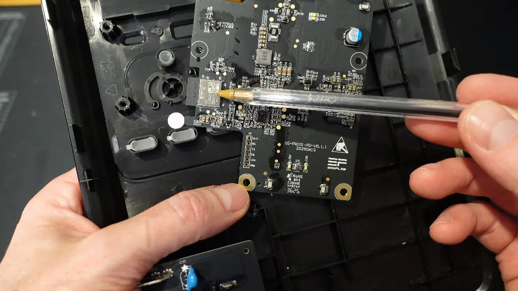
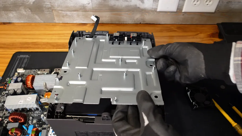
I identified the RX/TX communications pins on the board, which likely serve as the programming interface. I wanted to see if I could interact with the board outside of the power station. I found two screws holding the plastic insulators in place, but after I removed them, I realized the assembly was also secured with adhesive.
Accessing the Battery Pack
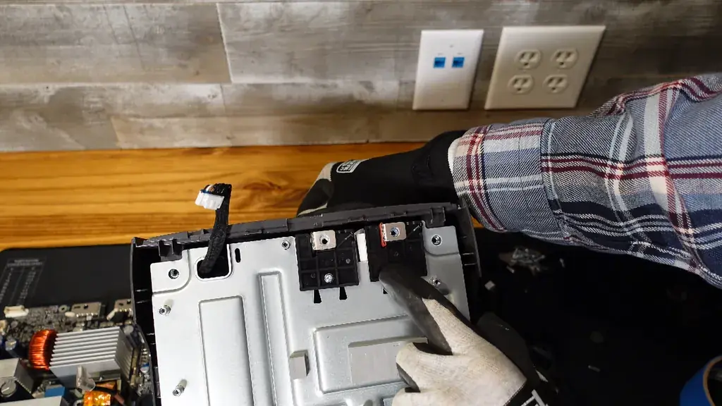
I wiggled the battery pack out of the chassis very carefully. I was surprised to find only three aluminum case prismatic cells. This configuration results in a 9.6V nominal voltage, which is quite small for this type of power station. It was a compact setup, but it certainly explained the lower capacity.
Identifying Temperature Sensors
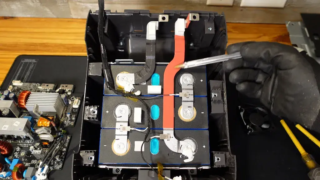
I inspected the battery pack for temperature monitoring. I found two sensors affixed near the negative terminal. I also counted three balance leads, which means the negative terminal itself is acting as the reference point for the fourth connection. The wiring was straightforward enough to trace.
Checking Bus Bar Construction
I looked at the bus bars, which were welded nicely to the cells. I noticed expansion humps in the metal to account for thermal movement. The balance leads were soldered onto nickel strips, which were then laser or spot-welded to the bus bars. Four screws held the entire pack in place within the frame.
Inspecting Cell Insulation
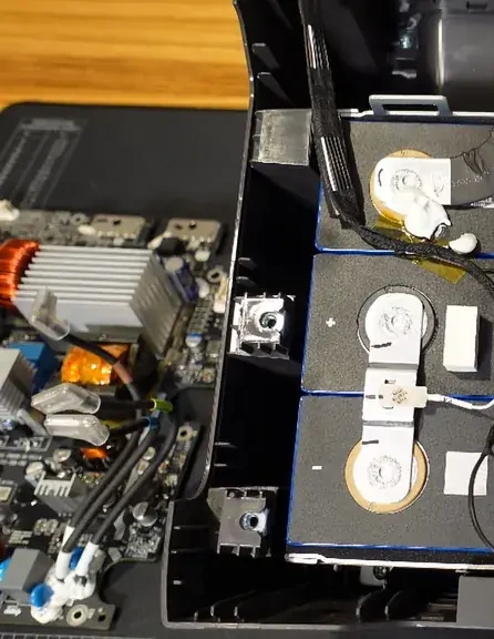
I examined the end plates, which were made of steel with foam padding between the plate and the cell. I found similar thin foam pieces between the individual cells to prevent vibration. Stainless steel bands wrapped around the entire assembly to keep the cells compressed and fixed in position.
Evaluating Cell Brand Quality
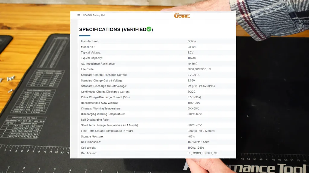
I was a bit disappointed to see these cells after finding EVE cells in my previous EcoFlow teardown. These are Goan cells; they aren't necessarily bad, but they are a budget-tier option. I typically see a reduced cycle life with this brand compared to premium alternatives like EVE.
Final Assessment of the Unit
I finished my inspection of the Delta 3 1000 Air. The internal design is essentially one battery pack and one main circuit board. It's a simple, cost-reduced architecture. I'll look for a larger power station for my next teardown to see how the build quality compares at higher price points.
⚠️ CAUTION: SAFETY WARNING!
Lithium batteries are dangerous and can result in fire. Do not attempt to modify or disassemble these packs without professional training.
Summary & Tips
I found the internal construction of the Delta 3 1000 Air to be a straightforward, cost-optimized design. While the use of Goan cells is a step down from what I've seen in other EcoFlow units, it explains the aggressive price point. I'm glad I opened it up to see exactly what's inside. I'll be looking for a more robust unit for my next project.
📋 FAQ
❓ Is the battery pack user-replaceable?
Usually, these packs are not considered user-replaceable due to the spot-welded connections and internal security. You'd need to be comfortable with high-current electrical systems to attempt a swap. It's safer to contact the manufacturer for service.
❓ Why did I see only 9V on the battery?
It's likely the BMS entered a protection mode or the cells were deeply discharged. This prevents the unit from charging until the system is reset.
❓ Can I use this board for a DIY project?
Technically, the board is proprietary and tightly integrated with the specific BMS and display communication protocols. You'd face significant challenges trying to repurpose it for a custom build. It's better to stick with standard off-the-shelf inverter components for DIY tasks.
❓ Are Goan cells reliable?
They are a budget-friendly option often found in entry-level electronics. While they function, they typically don't offer the same cycle life as premium brands like EVE. I'd expect lower long-term performance compared to higher-end cells.
Disclaimer: I purchased all tools for this guide with my own money to ensure an unbiased review. This post contains affiliate links, meaning I earn a small commission if you make a purchase at no extra cost to you.