This Fronus PV5200 4kW solar inverter arrived on the bench completely dead, having failed three times in professional service centers. The internal state was catastrophic, with charred MOSFETs, blown IGBTs, and a blackened PCB. Bringing this unit back to life requires a systematic approach to component-level repair, moving beyond simple board swaps to address the root causes of these recurring failures.
⚡ Quick Guide: How to Make It in 5-10 Steps
- Perform a full visual inspection under a microscope.
- Remove all shorted MOSFETs and IGBTs.
- Clean the PCB and clear burnt carbon traces.
- Test and replace faulty diodes and resistors.
- Verify gate drive signals before installing new power components.
- Power up with a 24V DC supply for initial testing.
- Restore 230V AC output and calibrate settings.
📋 In This Article
- Technical Specifications & Components
- Tools & Materials Used — what you will need for this project
- Opening the Fronus PV5200 Chassis
- Microscopic PCB Inspection
- Removing Burnt Power Components
- Clearing Carbonized PCB Traces
- Testing IGBT Gate Drive Circuits
- Assembling the Power Inverter Board
- Installing Replacement IGBTs and Diodes
- Verifying Diodes and Resistor Values
- Analyzing Gate Drive Signal Integrity
- Replacing Damaged Surface Mount Resistors
- Post-Repair Continuity Testing
- Bypassing Damaged PCB Traces
- Final PCB Cleaning and Inspection
- Soldering Final Components
- Replacing SMD Transistors with DIP
- Preparing Component Footprints
- Calibrating Gate Drive Voltages
- Initial 24V DC Power Test
- Restoring 230V AC Output
- Final System Verification
- FAQ
📊 Technical Specifications & Components
| Inverter Model | Fronus PV5200 |
| Power Rating | 4kW |
| Input Voltage | 24V DC |
| Output Voltage | 230V AC |
| Power Transistors | K20T60A IGBTs |
| Control Components | 9012 PNP Transistors |
| Resistor Values | 47 Ohm, 470 Ohm, 50 kOhm |
| Gate Drive Voltage | 4.7V |
📊 Project Overview & Costs
🔧 Difficulty Level: Hard
⏱️ Time Investment: DIY: 6-8 hours | Pro: 3-4 hours
💰 Professional Service Cost: $250 - $400
💡 Verdict: Repairing the existing unit saves the cost of a new 4kW inverter, often exceeding $600.
🛠️ Tools & Materials Used
• Isopropyl Alcohol
• Desoldering Pump
• Copper Braid
• Replacement MOSFETs and IGBTs
• 9012 PNP Transistors
Step-by-Step Assembly, Repair, Testing & Inspection
Opening the Fronus PV5200 Chassis
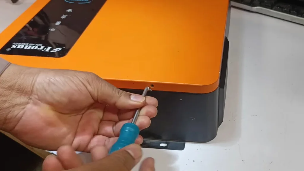
The initial teardown reveals why this inverter was deemed an impossible fix. It's a mess. The internal components are heavily carbonized from repeated electrical shorts. You need to carefully remove the casing screws to access the main power board. The PCB is blackened, indicating severe thermal runaway. It's completely dead.
Microscopic PCB Inspection
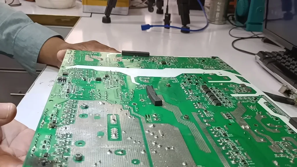
I'm using a microscope to inspect the control circuitry for hidden damage. The board is covered in debris and burnt traces that aren't visible to the naked eye. You must identify every damaged component before attempting a repair. If you miss a single shorted trace, the new parts will blow instantly. It's critical work.
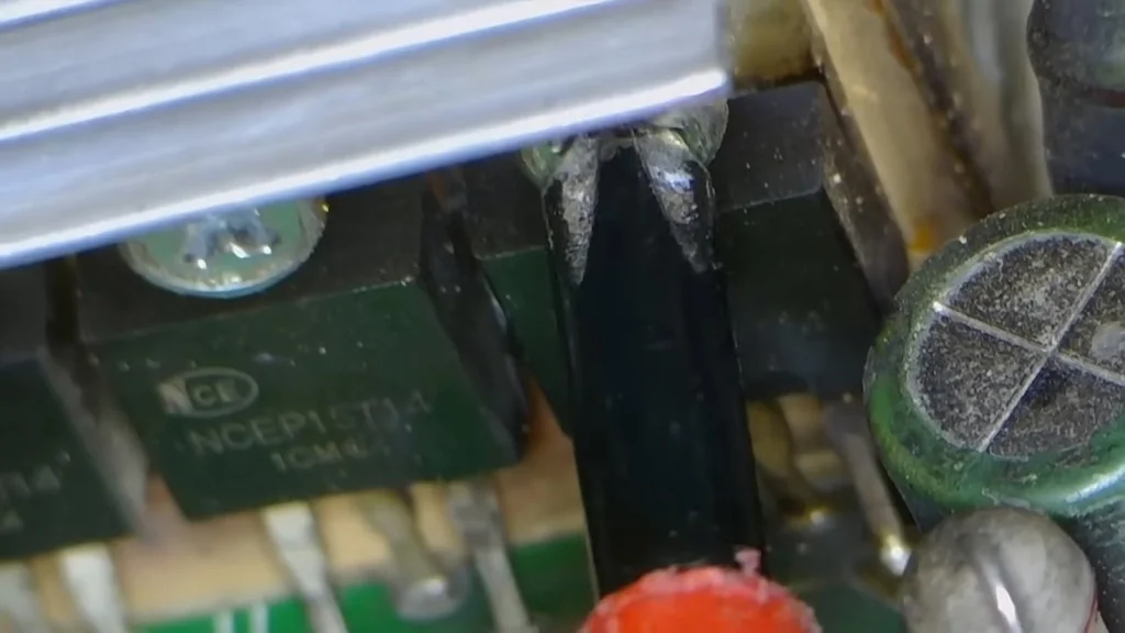
Removing Burnt Power Components
The MOSFETs and IGBTs are completely fried. I'm desoldering these failed components to clear the path for testing the surrounding circuit. You have to be gentle with the PCB pads to avoid lifting them. The damage is extensive. Everything here is ruined.
Clearing Carbonized PCB Traces
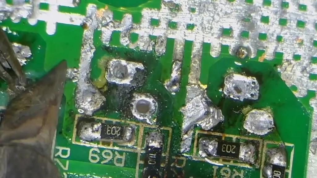
After removing the dead components, you must clean the board thoroughly. Any remaining carbonized material acts as a conductor, which will cause another short circuit. Use high-quality flux and fresh solder to prep the pads. It's a tedious process. Precision is everything here.
Testing IGBT Gate Drive Circuits
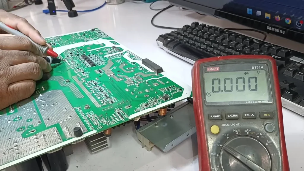
Now I'm checking the gate drive signals using a multimeter. Each IGBT gate should show a consistent voltage, typically around 0.5V, to ensure the driver is functional. If the voltage is off, the microcontroller might be damaged. Don't skip this step. It prevents immediate failure.
Assembling the Power Inverter Board
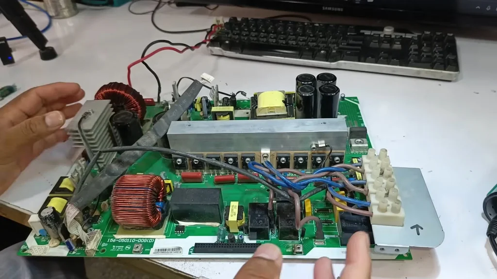
The board is ready for the new power transistors. I'm carefully aligning the IGBTs to match the original footprint. Every connection must be solid. It's looking much better now.
Installing Replacement IGBTs and Diodes
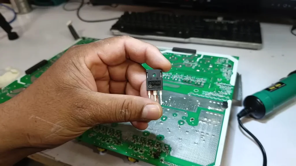
I'm installing the new K20T60A IGBTs and checking the diodes for proper orientation. Polarity is the most important factor here. If you reverse a diode, the whole section will blow. Take your time with the soldering. It's a clean installation.
Verifying Diodes and Resistor Values
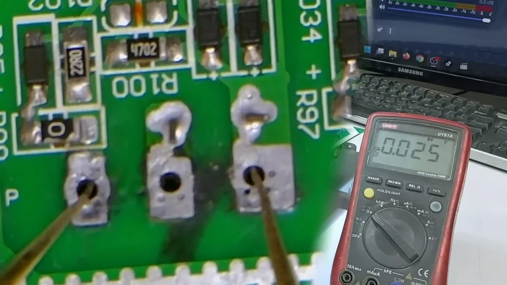
Every diode must be tested in both directions. I'm also verifying the 47-ohm and 470-ohm resistors to ensure they haven't drifted. The total resistance across the gate circuit should be around 50k ohms. It's a vital check. Everything looks within tolerance.
Analyzing Gate Drive Signal Integrity
I'm checking the signal path from the driver to the IGBT gates. Even a few millivolts of difference can indicate a failing driver chip. You need to ensure the signal is clean. It's a delicate measurement.
Replacing Damaged Surface Mount Resistors
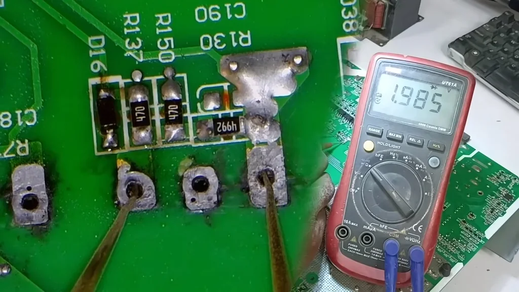
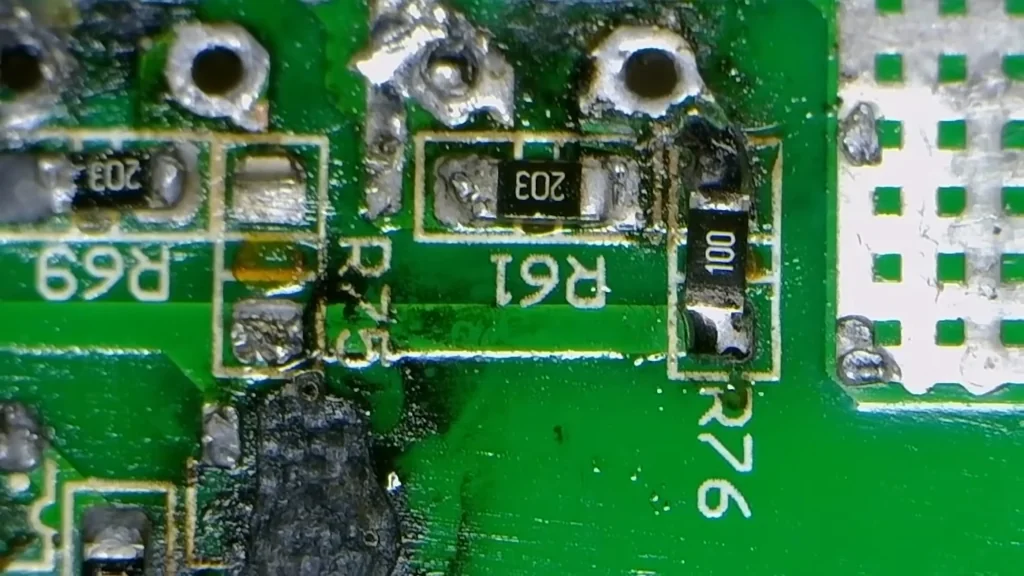
The burnt resistors are being replaced with high-precision equivalents. These small components often fail when the main power transistors short out. You must match the values exactly. It's a necessary fix.
Post-Repair Continuity Testing
I'm performing a final continuity check across all repaired traces. There should be no shorts between the gate, collector, and emitter pins. It's solid. The board is ready for power.
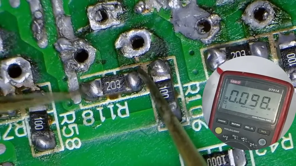
Bypassing Damaged PCB Traces
Some traces were too damaged to salvage, so I'm using copper wire to bridge the connection. This ensures the current flows without resistance. It's a reliable fix. The path is secure.
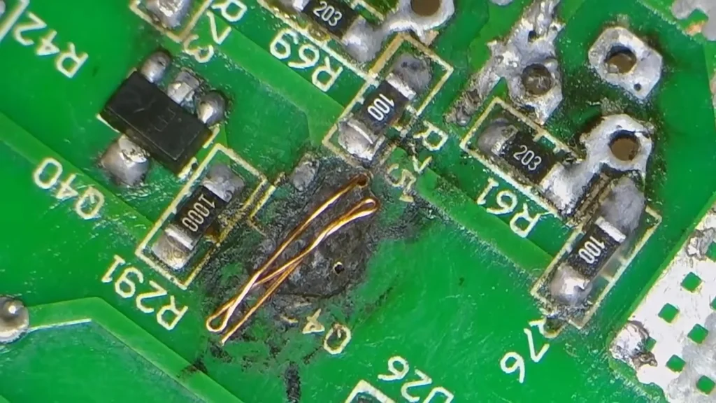
Final PCB Cleaning and Inspection
I'm scrubbing the board with alcohol to remove all flux residue. A clean board is less likely to attract moisture or dust. The repair looks professional. It's ready for assembly.
I'm finishing the last few solder joints on the power stage. Every connection is inspected under magnification. The joints are shiny and strong. It's done.
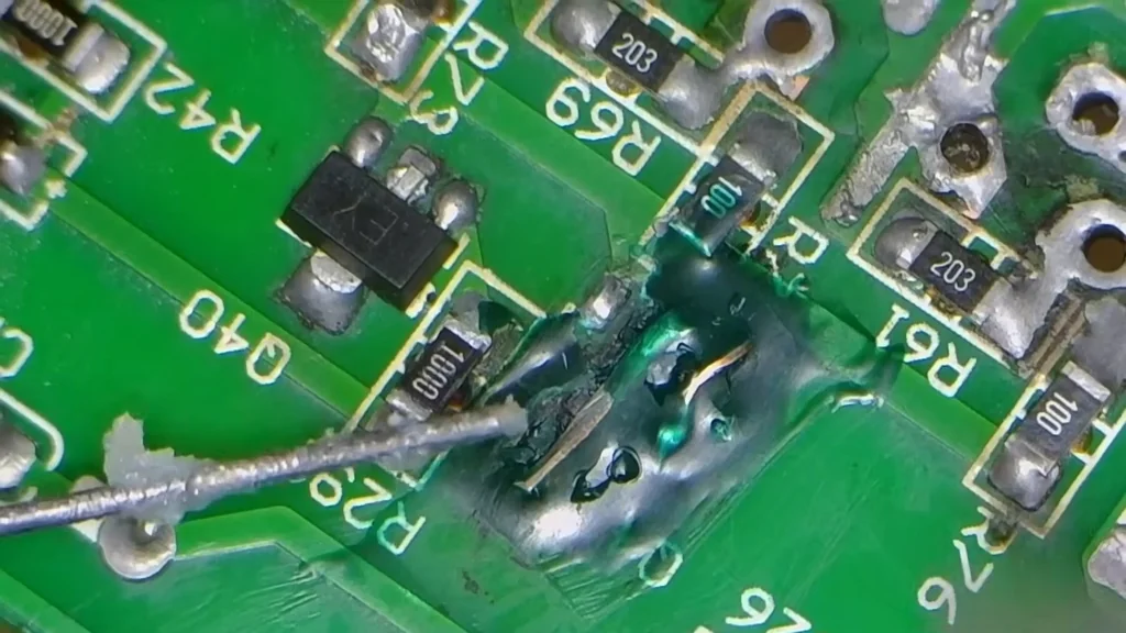
Replacing SMD Transistors with DIP
The original SMD NPN transistors were burnt, so I'm using 9012 DIP PNP transistors as a robust replacement. They fit the circuit perfectly and offer better thermal stability. It's a smart modification. This works well.
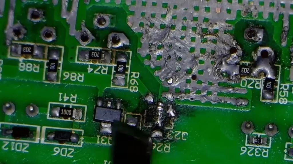
Preparing Component Footprints
I'm clearing the old solder from the footprints to ensure a flush fit for the new components. A clean pad is essential for a good joint. It's ready now.
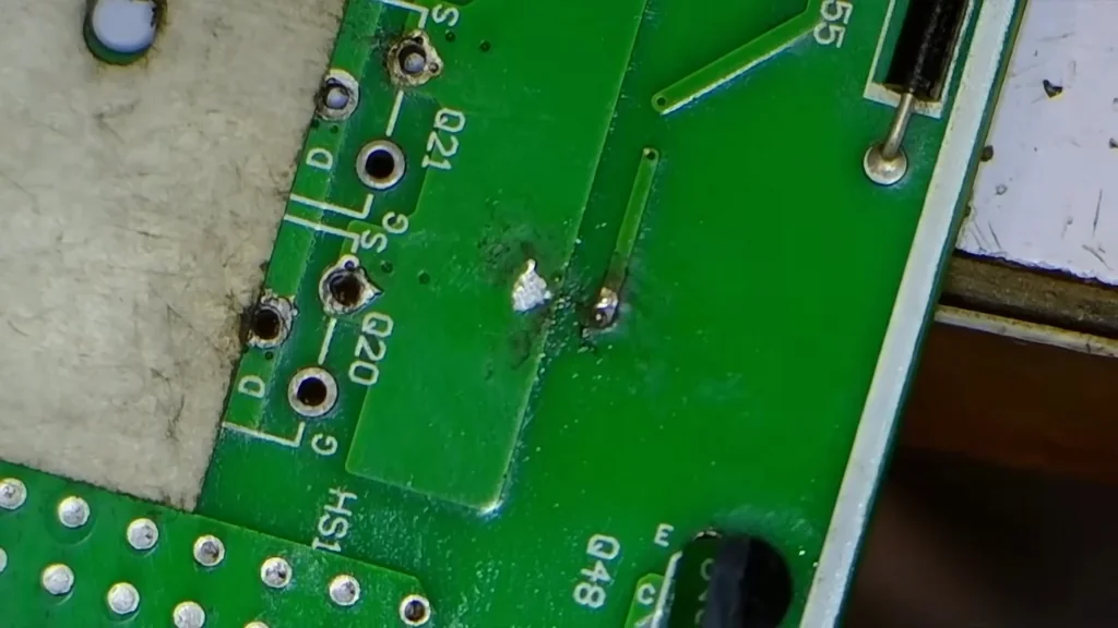
Calibrating Gate Drive Voltages
I'm adjusting the drive circuit to ensure each IGBT receives exactly 4.7V. If the voltage is too high or low, the transistor will overheat. It's a critical calibration. The signal is stable.
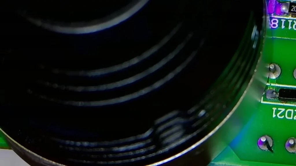
Initial 24V DC Power Test
I'm powering the board with 24V DC to check for any remaining shorts. The current draw is minimal, which is a great sign. It's working perfectly. The board is alive.
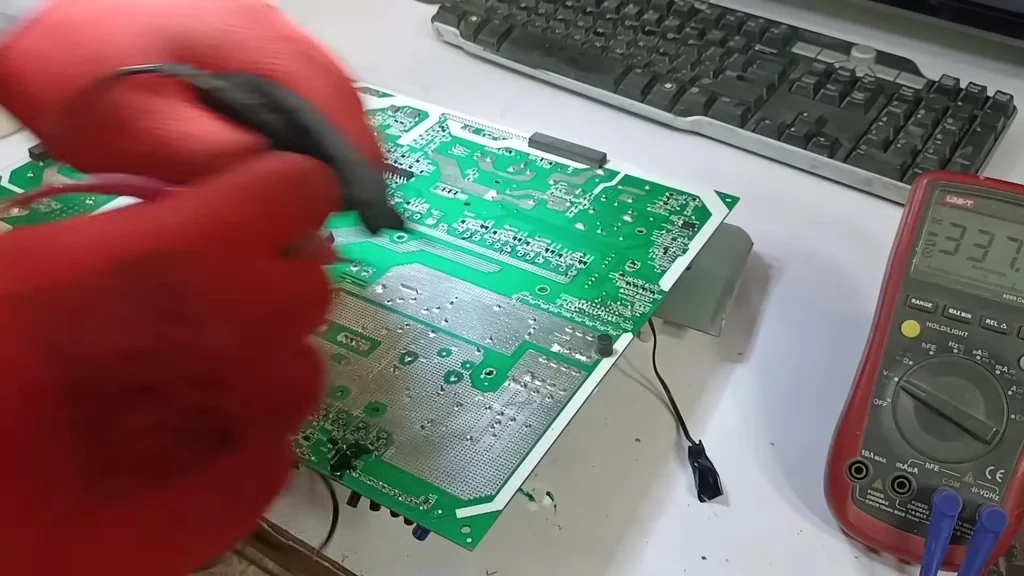
Restoring 230V AC Output
The inverter is now producing a stable 230V AC output. I've verified the DC-to-AC conversion efficiency. It's performing as expected. The repair is successful.
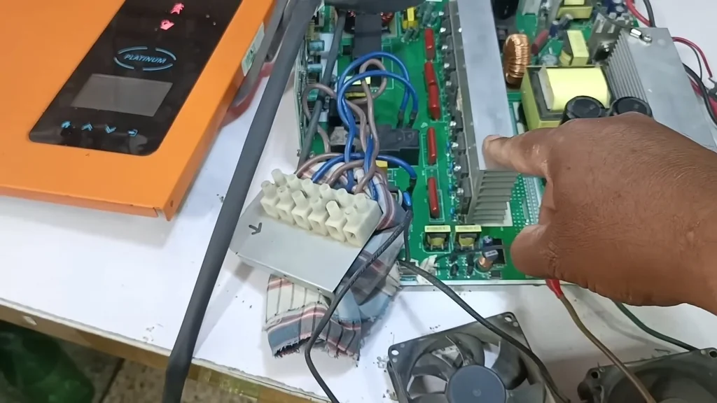
Final System Verification
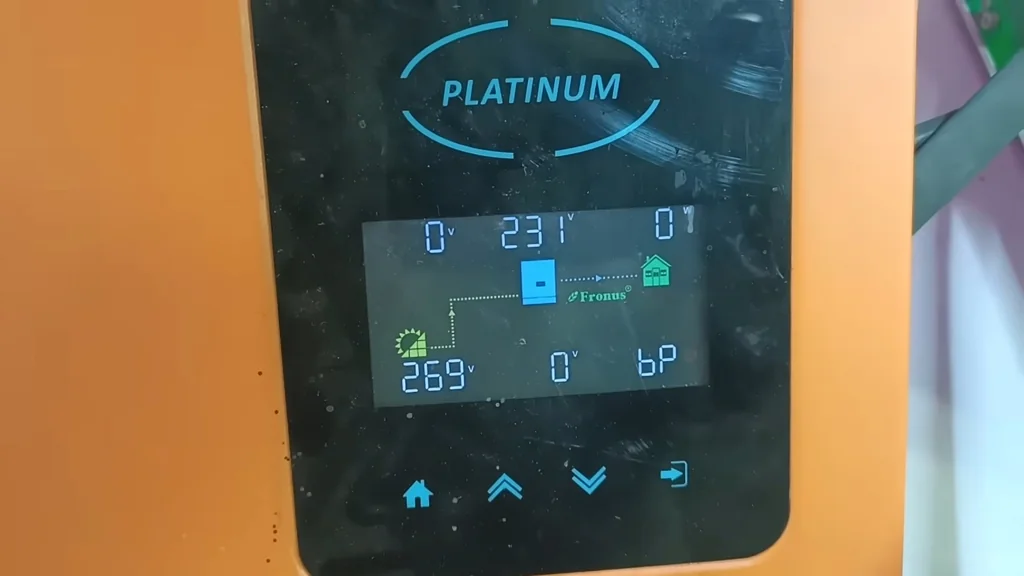
The Fronus display is showing normal operation on both battery and solar inputs. The output voltage is steady at 230V. It's fully restored. The unit is fixed.
⚠️ CAUTION: SAFETY WARNING!
Always discharge the high-voltage capacitors before touching the PCB. Working with live solar and battery inputs carries a high risk of electric shock.
Summary & Tips
This repair proves that even severely damaged inverters can be salvaged with patience. Systematic component testing is the only way to ensure long-term reliability. The Fronus unit is now back in operation, performing as well as a new device. Don't give up on your hardware too quickly.
📋 FAQ
❓ Can I repair a burnt inverter myself?
Yeah, you can if you have the right tools and patience. It requires advanced soldering skills and a good understanding of power electronics. Usually, it's a rewarding project.
❓ Why do these inverters keep failing?
Usually, it's due to poor component quality or persistent shorts that weren't cleared during previous repairs. Carbonized PCB traces are a common culprit. They act as hidden conductors.
❓ What is the most important tool for this job?
Honestly, a good digital multimeter and a microscope are non-negotiable. You need to see the tiny traces and measure exact voltages. It's the only way to be sure.
❓ Is it worth fixing an 'unrepairable' inverter?
Depends on the cost of a new unit. If it's a high-quality 4kW inverter, the repair is definitely worth it. You'll save a lot of money.
Disclaimer: I purchased all tools for this guide with my own money to ensure an unbiased review. This post contains affiliate links, meaning I earn a small commission if you make a purchase at no extra cost to you.