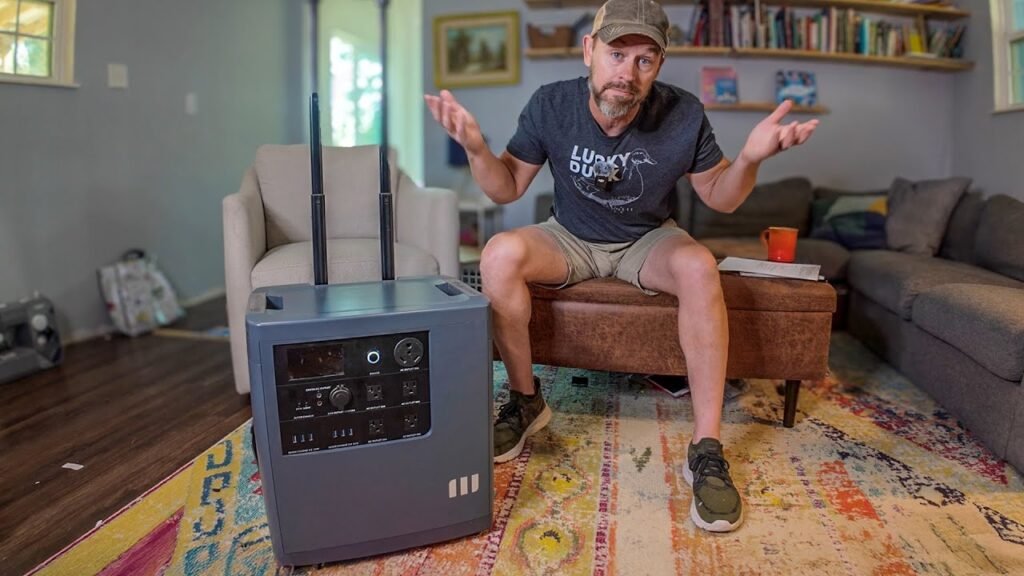
The Gobel Power Project X1 is a transparent DIY battery enclosure designed to house 16 EVE MB31 314Ah LiFePO4 cells in a vertical orientation. This kit provides a robust, modular framework for high-capacity energy storage, allowing for visual inspection of the cell stack. It is a straightforward build for those familiar with lithium battery safety and busbar installation.
⚡ Quick Guide: How to Make It in 5-10 Steps
📋 In This Article
- Technical Specifications & Components
- Tools & Materials Used — what you will need for this project
- Unboxing the Project X1 Kit
- Preparing the Base and Casters
- Installing the Cell Stack
- Securing the Cell Frame
- Installing the Busbars
- Mounting the Top PCB and BMS
- Assembling the Circuit Breaker Bracket
- Installing the Main Fuse
- Finalizing BMS and Output Connections
- Stacking the Battery Cages
- Connecting the Final Busbars
- Securing Terminals and Covers
- Wiring the Display and Buttons
- Reviewing the Completed Build
- Final Observations and Verdict
- FAQ
📊 Technical Specifications & Components
| Kit Name | Gobel Power Project X1 |
| Cell Compatibility | 280Ah or 314Ah LiFePO4 |
| Cell Type | EVE MB31 (3.2V) |
| Busbar Thickness | 1.9mm |
| Max Post Torque | 6 Nm (53 in-lbs) |
| Fuse Rating | 250A Westing Fuse |
| Fuse Interrupt Rating | 200,000A |
| PCB Part Number | 1155A |
📊 Project Overview & Costs
🔧 Difficulty Level: Medium
⏱️ Time Investment: DIY: 3-4 hours | Pro: 1.5 hours
💰 Professional Service Cost: $150 - $250 labor
💡 Verdict: Building this kit yourself saves significantly on pre-assembled battery costs while providing full visibility into the cell health.
🛠️ Tools & Materials Used
• Phillips Screwdriver
• 13mm Socket Wrench
• Epoxy Board Insulators
• Serrated Flange Nuts
Step-by-Step Assembly, Repair, Testing & Inspection
Unboxing the Project X1 Kit
The Project X1 is a specialized DIY battery enclosure. It supports 16 high-capacity LiFePO4 cells. The transparent case is the standout feature. It allows for immediate visual inspection of the internal cell stack. The design forces an upright vertical orientation. This is a solid design choice for long-term cell health. It's a clean kit.

Preparing the Base and Casters
Assembly starts at the bottom. You need to attach the casters to the support bracket. Use the provided Phillips screws for this. Both frames are identical. It doesn't matter which one sits on top. I'm using EVE MB31 cells for this build. They are 3.2V, 314Ah units. It's a heavy stack.

Installing the Cell Stack
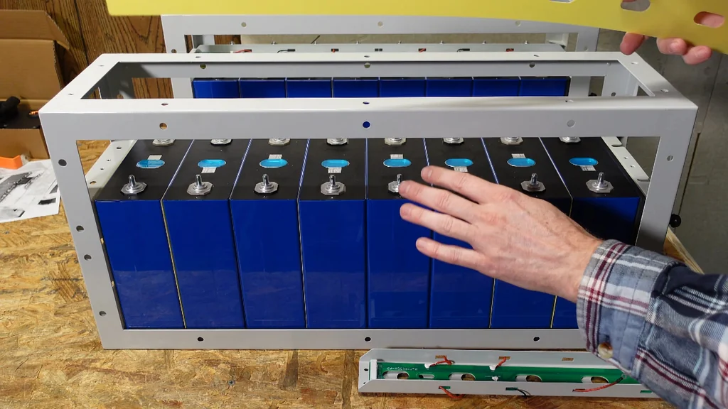
You must alternate the polarities carefully. Place a cell, then an epoxy board, then the next cell. Keep the pattern consistent. Before the last cell, install the end plate. Note the notch on the side. It points down during installation. Slide the final cell in gently. Don't forget the last insulator. It's a tight fit.

Securing the Cell Frame
I used a drill for the screws. The clutch was set to the lowest setting of one. This provided the perfect amount of tension. The cells are now fixed in place. They aren't loose, but they aren't crushed either. You could still wiggle one out if necessary. Next, place the fiberglass covers over the vents. It's ready for busbars.

Installing the Busbars
The busbars are 1.9mm thick. They feature a center hole for balance leads. Place them carefully across the terminals. The main positive terminal remains bare for now. The first bar goes in the back. Subsequent bars bridge cells two and three. Use the serrated flange nuts. Torque to 6 Nm or 53 in-lbs.

Mounting the Top PCB and BMS
Place the epoxy board insulator on top. The PCB bar is part number 1155A. It covers cells A0 through A8. Now, switch to the BMS assembly. Connect the two red cables. Don't forget the ribbon cable on the bottom. It's a delicate process. Take your time here.
Assembling the Circuit Breaker Bracket
Secure the board with the six long, thin screws. Plug in the three communications cables. The Chint circuit breaker logo faces forward. Install the four tabs into the main terminals. I should have done this before mounting the bracket. It's easier that way. Put it back on the bracket now.

Installing the Main Fuse
The kit includes a 250A Westing fuse. It has a 150V DC rating. The interrupt current is 200,000A. It sits on the standoffs with a 13mm bolt. Thread them on loosely for now. I made a mistake with the BMS screws earlier. I'm swapping them for the correct ones now.

Finalizing BMS and Output Connections
Use the correct screws this time. The smaller busbar with 90-degree bends goes on the circuit breaker output. Set the BMS on top of the pack. It covers cells 1 through 8. Secure it with the side holes. The bent busbar connects the BMS to the main pack. It's a precise fit.

Stacking the Battery Cages
Stacking is easier on the ground. I'm doing it on the bench for the video. Use the 10mm bolts to secure the frame. It connects to the bottom plate. Don't roll it off the bench. That would be a disaster. The second cage is ready to go.

Connecting the Final Busbars
The last busbar is for the bottom pack positive. It's a large, distinct bar. Manage the balance lead harnesses carefully. One is about a foot longer than the other. The long one goes to the bottom pack. Don't mix them up. You will ruin the BMS. Connect to B0 through B8.

Securing Terminals and Covers
Peel back the protective plastic. Insert the terminal from the outside. Add the screw and nut on the inside. Tighten by hand. Don't crack the plexiglass. Use the Phillips screws with built-in washers for the cover. Connect the positive and negative busbars. It's almost finished.

Wiring the Display and Buttons
The button mounts on the front. The connector is a bit strange. It looks like a six-pin connector. The harness only has three pins. Only two conductors are connected. One is black. Match it to the BMS port. It's a simple pinout check.

Reviewing the Completed Build
That's the full assembly. I love the transparent case. You can see the cells clearly. Is it necessary? Probably not. But it's great for inspection. The upright orientation is best. It handles expansion well. It's a solid kit.

Final Observations and Verdict
Cells expand over time. The flexible busbars help reduce tension. The bottom balance lead was a bit short. It needs another 3 or 4 inches. Aside from that, it's a fantastic case. I'm thinking about buying a second one. It's worth it.
⚠️ CAUTION: SAFETY WARNING!
Lithium batteries store massive amounts of energy and pose a severe fire risk if shorted or improperly handled. Always verify polarity with a multimeter before making any connections.
Summary & Tips
The Project X1 kit offers a high-quality, transparent solution for DIY energy storage. Assembly is straightforward provided you follow the polarity and torque requirements. The upright cell orientation is a superior choice for long-term battery health. It is a highly recommended kit for anyone looking to build a custom LiFePO4 bank.
📋 FAQ
❓ Can I use different cells in this kit?
Usually, yes. It is designed for 280Ah or 314Ah cells. Check your cell dimensions first. They must fit the frame.
❓ Is the transparent case strong enough?
Yeah, it's quite robust. The metal frame provides the structural support. The plexiglass is mainly for protection and visibility.
❓ Do I really need a torque wrench?
Honestly, you do. Over-tightening can crack the terminal blocks. Under-tightening causes heat buildup. Don't skip this step.
❓ What happens if I mix up the balance leads?
It's bad news. You will likely fry the BMS. Always double-check the labels before plugging them in.
Disclaimer: I purchased all tools for this guide with my own money to ensure an unbiased review. This post contains affiliate links, meaning I earn a small commission if you make a purchase at no extra cost to you.