The RV solar system was dead. No power coming in, despite clear skies in the desert. We were looking at zero watts when it should’ve been pushing at least 230 watts. This wasn’t just an inconvenience; it was a critical failure for off-grid living. Fixing this solar charging issue and upgrading the charge controller became the top priority before the next big family trip.
⚡ Quick Guide: How to Make It in 15 Steps
- Identify the solar charging system failure points.
- Diagnose low voltage from solar array.
- Inspect and replace the faulty solar connector.
- Prepare and crimp new MC4-style connectors.
- Secure cable connections with heat shrink.
- Test system voltage after connector repair.
- Unbox and examine the new MPPT charge controller.
- Temporarily connect the upgraded charge controller.
- Verify performance and plan permanent mounting.
- Assess mounting location for the larger controller.
- Relocate existing DC-DC charger for space.
- Mount the new solar charge controller securely.
- Organize cables and plan Bluetooth module placement.
- Connect remaining accessories and secure wiring.
- Confirm full system functionality and charging.
📋 In This Article
- Technical Specifications & Components
- Tools & Materials Used — what you will need for this project
- Diagnosing the RV Solar Charging Failure
- Troubleshooting Low Solar Input Voltage
- Replacing the Corroded Solar Connector
- Crimping New MC4-Style Solar Connectors
- Reinforcing Cable Connections with Heat Shrink
- Verifying Voltage and Confirming Controller Failure
- Unboxing the New MPPT Charge Controller
- Temporary Installation and Performance Check
- Assessing Wire Gauge and Fuse Link Needs
- Planning the New Controller’s Mounting Location
- Relocating the EcoFlow DC-DC Charger for Space
- Securing the New Solar Charge Controller
- Organizing Cables and Bluetooth Module Placement
- Final Connections and System Activation
- Project Completion and Final Thoughts
- FAQ
📊 Technical Specifications & Components
| Original Charge Controller Cost | $30 |
| Expected Solar Power Output | At least 230W |
| Initial Measured Solar Voltage (Faulty) | ~3V |
| Measured Battery Voltage (Initial) | 13.9V |
| Measured Battery Voltage (Post-Repair) | 13.2V - 14.1V |
| Measured Solar Voltage (Post-Connector Fix) | 20.6V |
| Measured Solar Power (Post-Reconnect) | 194-195W |
| New Charge Controller Rating | 40A, 100V |
| New Charge Controller Observed Output | 264W, 19.3A |
| App Reported Solar Power | 275W |
| App Reported Charging Voltage | 14.1V |
| App Reported Solar Voltage | 15.1V |
| Actual Battery Voltage (Multimeter) | 13.5V |
| Previous Inverter (from old owners) | 200W |
📊 Project Overview & Costs
🔧 Difficulty Level: Medium
⏱️ Time Investment: DIY: 4-6 hours | Pro: 2-3 hours
💰 Professional Service Cost: $300-$600
💡 Verdict: DIY saves significant labor costs, especially when dealing with specialized RV electrical systems.
🛠️ Tools & Materials Used
• Solar Crimp Kit
• Heat shrink
• Lighter
• Screws
• Starlink
• EcoFlow DC-DC charger
Step-by-Step Guide
Diagnosing the RV Solar Charging Failure
The solar system in the RV was completely dead, showing zero watts coming in despite being out in the desert with clear skies. This wasn't right. Normally, under these conditions, it should be cranking out at least 230 watts. Something was seriously off. I was worried it was either the solar charging connector or the cheap $30 charge controller itself. Fuses on the battery side checked out fine, reading around 13.9 volts, so the problem wasn't there. The issue was clearly on the solar input side. No power. This needed a fix, and fast, because reliable power is everything when you're off-grid.
Troubleshooting Low Solar Input Voltage
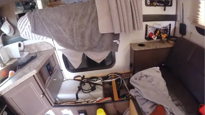
After confirming the battery side was good, I probed the solar input at the charge controller with a multimeter. It only showed about 3 volts. That's terrible. This confirmed the problem was definitely before the controller, or the controller itself was shot. My prime suspect was a specific cable connector on the roof. I'd noticed it looked a bit warped and sun-damaged during the second panel install, almost like it had melted. I knew it was a cheap part when I first put it in. All the other connectors checked out, but this one looked compromised, likely allowing water in and causing corrosion. No surprises here. The plan was to tackle that connector first; if that didn't fix it, then it was time for a new charge controller.

Replacing the Corroded Solar Connector
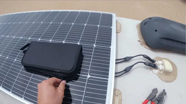
Turns out, the cheap solar connector was completely shot. When I pulled it apart, the male end practically fell off in my hand. You could see clear evidence of water intrusion and discoloration inside the connector, which is a death sentence for electrical connections. This thing was toast. It explains the intermittent charging issues and the low voltage readings. I disconnected the solar charge controller to ensure safety before working on the wiring. Good to go. I then tried to salvage as much cable as possible, cutting back the damaged section. The wire underneath the discolored insulation looked surprisingly decent, not burnt, so I had a good section to work with for the new connector. Sometimes you get lucky.
Crimping New MC4-Style Solar Connectors
The discoloration on the wire, thankfully, wasn't from burning; it looked more like some weird paint residue. The internal wires were clean. That's a relief. I trimmed the cable back to fresh copper, ready for the new connector.
I had to figure out which end of the new MC4 connector was positive and negative, and which was male and female for the connection.
I decided to start with the female connector first, just to get a feel for the crimping process with the new tools. Honestly, the first one was a bit of a pain, but practice makes perfect. It was scorching hot up on that roof, so hot my GoPro actually shut down, but I got the crimp done right. The new crimpers, which came in a kit from Amazon, worked surprisingly well. Definitely a step up from whatever cheap tools I used last time. Now, just gotta push the piston and twist it on. That's the whole trick.

Reinforcing Cable Connections with Heat Shrink
The real challenge up on the roof was the limited cable slack. I tried to pull more wire out of the conduit, and I managed to get a bit more, but I ended up nicking the outer braiding in the process. It happens. To prevent future issues with water intrusion or abrasion, I decided to use heat shrink tubing over the damaged section and the new connection point. This provides a robust, weatherproof seal.
I grabbed a lighter to shrink the tubing down tight. It's a quick and dirty method, but it works like a charm. The sun was beating down hard, making the heat shrink process even faster. Once the heat shrink was snug, the connection felt solid. Now, with the roof connector fixed, it was time to head back inside and see if the solar charge controller would finally show some life. No charge. Still nothing. What the hell?

Verifying Voltage and Confirming Controller Failure
Still no charging after the connector repair. What was going on? I pulled out the multimeter again to double-check everything. First, I measured the battery terminals, showing a healthy 13.2 volts. That's correct. Then, I checked the solar input on the controller, and it read 13.3 volts. That's what it should be.
Next, I pulled the fuse on the battery side to disconnect the controller from the battery. The battery voltage reading disappeared, as expected.
Then, I measured the open-circuit voltage coming directly from the solar panels. 20.6 volts. That's correct. This confirmed the panels were putting out power and the new connector was good. The old charge controller was definitely dead. It failed. I tried disconnecting and reconnecting all the solar panels one by one, and then both together. Suddenly, I started seeing around 194-195 watts from the sun. I even turned off the inverter to avoid any interference with the measurements. It was charging!

Unboxing the New MPPT Charge Controller
All of a sudden, the old controller was charging, hitting 203 watts. My panels are rated for 200 watts, so that was interesting. It was a weird turn of events, but I wasn't going to trust that old $30 unit for long. My new charge controller package arrived right on time. This thing came with a small Bluetooth connector, which is pretty cool for monitoring on my phone.
I unboxed the new controller, and wow, it was significantly larger than the tiny one I had installed previously. It's built for serious power. This unit is rated for 40 amps and, I think, 100 volts, meaning it should pull a lot more juice from the roof panels. Right now, with the old controller, it's putting out about 150 watts and around 11 amps at 13.4 volts, but that's with some clouds rolling in. Let's see what this beast can do.

Temporary Installation and Performance Check
The new controller is rated for 100 volts, and theoretically, we should be getting a lot more energy from those roof panels. Sure enough, the readings on the old system jumped back up to 195 watts when the clouds cleared. Now, it was time to hook up this new monster. I connected it temporarily, not bothering with permanent mounting just yet. I just wanted to see if it worked better.
I simply set it aside for the initial test.
This unit needs to be mounted vertically for proper heat dissipation, especially with the amount of power it's designed to handle. But just a temporary hookup showed an immediate, massive improvement. We were getting 264 watts and 19.3 amps from the same solar setup! That's significantly more electricity flowing into the batteries. It's solid. Plus, it came with a temperature sensor for the battery, which is a neat feature to prevent overheating, and a Bluetooth module for phone monitoring. Very cool.

Assessing Wire Gauge and Fuse Link Needs
The new charge controller's Bluetooth module is a sweet perk; I can connect it to my phone and keep an eye on everything. However, a new issue popped up: the fuse wire on the battery side was getting seriously hot. This thing needs an upgrade. That's a problem. It runs straight to the battery terminal, and while the main cable looks okay, that fuse wire is definitely undersized for the increased current. I'll need to order a heavier gauge fuse link for that.
Mounting this big controller permanently is going to be a challenge. It's massive. But right now, we're already seeing 14.1 volts at the battery, which is just incredible. The app, while a bit quirky, shows 275 watts from the solar panels and a charging voltage of 14.1 volts. The app's voltage reading is a bit off; my multimeter shows the actual battery voltage is 13.5 volts. It's probably showing the combined voltage with the solar input, not just the battery itself.
Planning the New Controller's Mounting Location
The actual battery voltage, if I measured it directly, sits around 13.5 volts. That's a more accurate reading than what the app might show, which probably factors in the incoming solar power. The previous owners had a tiny 200-watt inverter here, probably for their computers, and they drilled a hole in the wall that I still haven't been able to properly seal. What a mess.
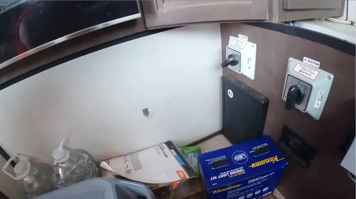
I thought about mounting the new controller right there, as it would line up nicely with the existing cable runs.
But here's the deal: this new controller is incredibly thick and bulky. It would stick out a good distance from the wall. I don't have much space in this area. I really don't know where else to put it because all the solar cables need to run directly to it. If I put it anywhere else, I'd have to extend all those heavy-duty cables, which is a royal pain and adds resistance. This whole area is becoming a technical service wall, but I still need to keep space free for water and supplies. It's going to take some thinking.

Relocating the EcoFlow DC-DC Charger for Space
Sometimes, you just need a break, grab some lunch, and let your brain chew on the problem for a bit. My solution for the mounting dilemma was to remove the EcoFlow DC-DC charger that was previously installed in the ideal spot. That was the best place for mounting the new, larger solar controller. Now, I won't be able to see the controller's screen directly, but that's what the Bluetooth module is for. I'll be able to monitor it right from my phone, no big deal.
This new placement offers a couple of key advantages.
First, the new controller needs good airflow for cooling. If it's too close to the wall, especially with that cheap paneling, it'll get seriously hot. Mounting it here gives it plenty of space behind it for proper ventilation. The only thing that still worries me a little is the overall ventilation in the area. I've got a small vent that leads outside, which I usually open in the summer. It's probably time to open it up now to help with airflow.
Securing the New Solar Charge Controller
The open vent will provide some much-needed extra airflow, which I hope will keep the new controller from overheating. I like this option better. Once I committed to the spot, there was no turning back. I found three suitable screws to mount the controller. These things are long, but they'll hold this unit solid. Three mounting points. It's not going anywhere. The mounting felt secure and robust.
Below the controller, the cables have just enough room for the battery connections. The battery itself isn't going to slide around, as its tray is firmly screwed to the floor. Everything is good to go. This looks dependable. With the main unit mounted, the next step was to figure out a good spot for that little Bluetooth module so I could easily see its indicator light and connect to it.

Organizing Cables and Bluetooth Module Placement
With the main controller locked down, I had to find a good spot for that Bluetooth module. I figured somewhere visible, so I could see its power indicator light, would be ideal. Maybe right here, inside the compartment. That would be pretty good. Or perhaps just above it. I decided on a spot where it would be easily accessible but out of the way.
As always, when working in this cramped space, I had to make sure all the cables and the main strap were properly routed and secured. I had to clear out some of Kirk's dog blanket from the area; this camper needs a serious cleaning. Seriously. I double-checked the connections. Everything was looking good. Now, only four main cables were left to manage: one for Starlink, the DC-DC charger from the generator going to the battery side, the generator power itself, and the AC input for the camper. Almost done.

Final Connections and System Activation
Alright, this camper is a mess, but we're getting there. I connected the Eagle Pro battery. Since we're currently hooked up to shore power, I simply connected the positive and negative terminals, bypassing the battery for now. No need for it to be connected to the main battery bank at this moment. I also left the Starlink plugged in directly; that's my little trick to keep it running when on shore power. Everything is buttoned up.
The new, more powerful charge controller is installed. It's a solid upgrade. Everything works again. This priority task is finally done. I'm keeping the old controller for small future projects, like maybe a tiny solar panel for the Suzuki. It's not completely broken, so it's worth holding onto. Honestly, we'll find a use for it. This was a big priority. Time to mark it off the list. I need to make a list of all this junk. So much going on. Okay, time to head inside; it's cooler in there.

Project Completion and Final Thoughts
The RV solar system is back in business, charging efficiently with the new controller. It's a relief to have reliable power again, especially when out in the middle of nowhere. The upgrade significantly boosted the charging capabilities and provides better monitoring. This project really highlighted the importance of not skimping on critical components like charge controllers. That cheap unit barely lasted, but the new one is a beast. Now, to tackle the rest of the projects piling up.

⚠️ CAUTION: SAFETY WARNING!
Always disconnect battery and solar inputs before working on any solar charging system to prevent electrical shock or damage to components. High current systems can be dangerous.
Summary & Tips
Getting the RV solar system back online was a critical fix, ensuring we have power for whatever comes next. The old, cheap charge controller was a bottleneck, and upgrading it made a massive difference in power capture. This project showed that sometimes you just gotta replace faulty components, especially when they're prone to failure. Now, with more reliable power, the camper is truly ready for the road.
📋 FAQ
❓ Why did the solar panels stop charging?
Honestly, there were two main culprits here. The primary issue was a corroded, sun-damaged solar connector on the roof, which likely let water in and caused a poor connection. On top of that, the old charge controller was a cheap, $30 unit that was likely on its last legs, showing inconsistent performance and eventually failing to charge. It's always a good idea to check the simplest points of failure first, like connectors, before blaming the more complex electronics.
❓ How do you diagnose a faulty solar charge controller?
First thing, you check the voltages. Use a multimeter to measure the battery voltage directly, then the voltage coming from the solar panels at the controller's input. If the panels are putting out good voltage (e.g., 20+ volts) but the controller isn't passing significant current or showing proper charging voltage to the battery, the controller is likely toast. Also, check for visual signs of damage, like melted wires or error codes on the display. In this case, the controller was only showing 3V from the solar side, which was a dead giveaway of a problem.
❓ What's the benefit of upgrading to a 40A, 100V charge controller?
Look, the bigger controller is a game-changer for a few reasons. A 40A rating means it can handle more current from your solar array, and 100V input allows for higher voltage panel configurations, which can be more efficient over longer cable runs. This translates to more watts and amps actually making it into your battery bank, especially when you've got multiple panels on the roof. The jump from around 200W to over 260W with the same panels after the upgrade is a clear example of that improved efficiency. It's a lot more power.
❓ Is a Bluetooth module for a charge controller really necessary?
Nah, not strictly necessary, but it's a huge convenience. The Bluetooth module lets you monitor your solar system's performance right from your phone. You can see real-time wattage, amperage, battery voltage, and charging status without having to physically check the controller's display, which might be tucked away in a hard-to-reach spot. It's a nice feature to have for quick checks, even if the app's voltage readings aren't always perfectly precise compared to a multimeter.
❓ Why did the fuse wire get hot after the upgrade?
The fuse wire got hot because the new charge controller was pulling significantly more current than the old one. The original wiring, including that fuse link, was likely sized for the lower output of the old $30 controller. When you start pushing 19.3 amps or more through a wire designed for much less, it's going to heat up. That's a fire hazard waiting to happen. You always need to match your wire gauge and fuse rating to the maximum current your system can produce. This thing needed an upgrade, plain and simple.
Disclaimer: I purchased all tools for this guide with my own money to ensure an unbiased review. This post contains affiliate links, meaning I earn a small commission if you make a purchase at no extra cost to you.