Recreating the iconic Macro Data Refinement (MDR) computer from the show Severance requires a precise blend of 3D printing and compact hardware integration. This build utilizes a Raspberry Pi 5, an NVMe SSD base, and a 5-inch DSI touchscreen to create a functional, portable desktop unit. By focusing on intentional design and custom mounting, you can house your server projects in a chassis that mirrors the show’s retro-futuristic aesthetic.
⚡ Quick Guide: How to Make It in 5-10 Steps
- Design and 3D print the MDR case components using matte blue and black filaments.
- Install threaded metal inserts into the printed chassis for secure assembly.
- Mount the Raspberry Pi 5 and NVMe base using provided spacers.
- Connect the 5-inch DSI touchscreen via the ribbon cable.
- Integrate a rocker switch and battery pack for portable power functionality.
- Assemble the front plate, camera module, and side ear knobs.
📋 In This Article
- Technical Specifications & Components
- Tools & Materials Used — what you will need for this project
- Planning the MDR Computer Build
- Refining the 3D CAD Design
- Preparing the Bottom Case Cover
- Installing the NVMe Base
- Mounting the Raspberry Pi and Display
- Assembling the Front Plate and Camera
- Locking the Chassis Components
- Integrating the Battery and Switch
- Finalizing the Main Body
- Constructing the Stand
- Attaching the Side Knobs
- Final Assembly Check
- Testing the Retro UI
- FAQ
📊 Technical Specifications & Components
| Main Board | Raspberry Pi 5 |
| Storage | 256GB NVMe SSD |
| Display | 13cm (5-inch) DSI Touchscreen |
| Power System | Portable Battery Pack with Pass-through Charging |
| Control Interface | Rocker Power Switch |
| Chassis Material | 3D Printed PLA |
| Connectivity | USB-C Power |
| Interface | JST Connectors for Internal Wiring |
📊 Project Overview & Costs
🔧 Difficulty Level: Medium
⏱️ Time Investment: DIY: 10-15 hours | Pro: 6-8 hours
💰 Professional Service Cost: $250 - $350
💡 Verdict: Building this custom chassis is significantly more affordable than sourcing vintage-style hardware enclosures.
🛠️ Tools & Materials Used
• 3D Printer
• Matte Blue eSUN Filament
• Black PLA Filament
• Metal Threaded Inserts
• JST Connectors
• Double-sided Tape
Step-by-Step Assembly, Repair, Testing & Inspection
Planning the MDR Computer Build
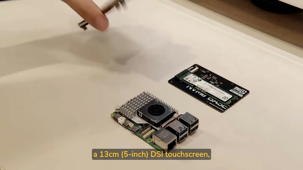
The foundation of this project relies on the Raspberry Pi 5, chosen for its robust performance in coding and server tasks. To achieve the aesthetic of the Macro Data Refinement (MDR) computers, I've selected a 13cm DSI touchscreen and an NVMe base with a 256GB SSD. Portability is key, so a battery pack is integrated into the design. I'm using a rocker switch for power control, which adds a tactile element seen in the show. Soldering JST connectors onto the switch and the Pi ensures reliable, easy connections. It's a solid start. Designing the curves for the case was the hardest part of the CAD process.
Refining the 3D CAD Design
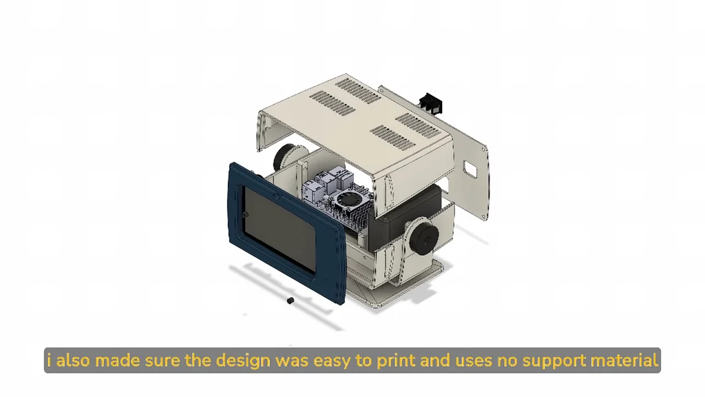
After weeks of iterative tweaking, the CAD model is finally ready for production. The design prioritizes printability, requiring no support material for the main body sections. You can find the STL files and a complete bill of materials on my Patreon page. I'm using OrcaSlicer to prepare the G-code for my Ender3v2 printer. The geometry is complex. Getting the curves right was tough.
Preparing the Bottom Case Cover
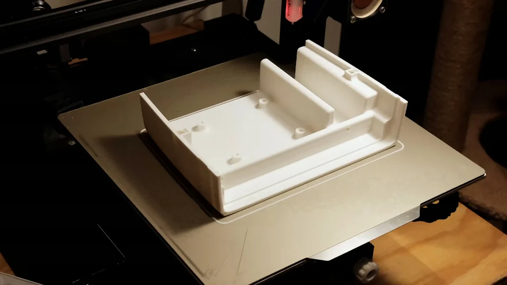
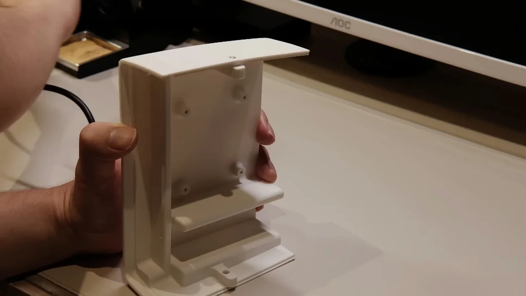
The bottom cover acts as the primary mounting point for the internal hardware. I'm installing metal inserts into the printed plastic to ensure the backing screws won't strip out over time. These inserts are also placed at the points where the stand bracket attaches. It's a necessary step. Durability matters for these builds.
Installing the NVMe Base
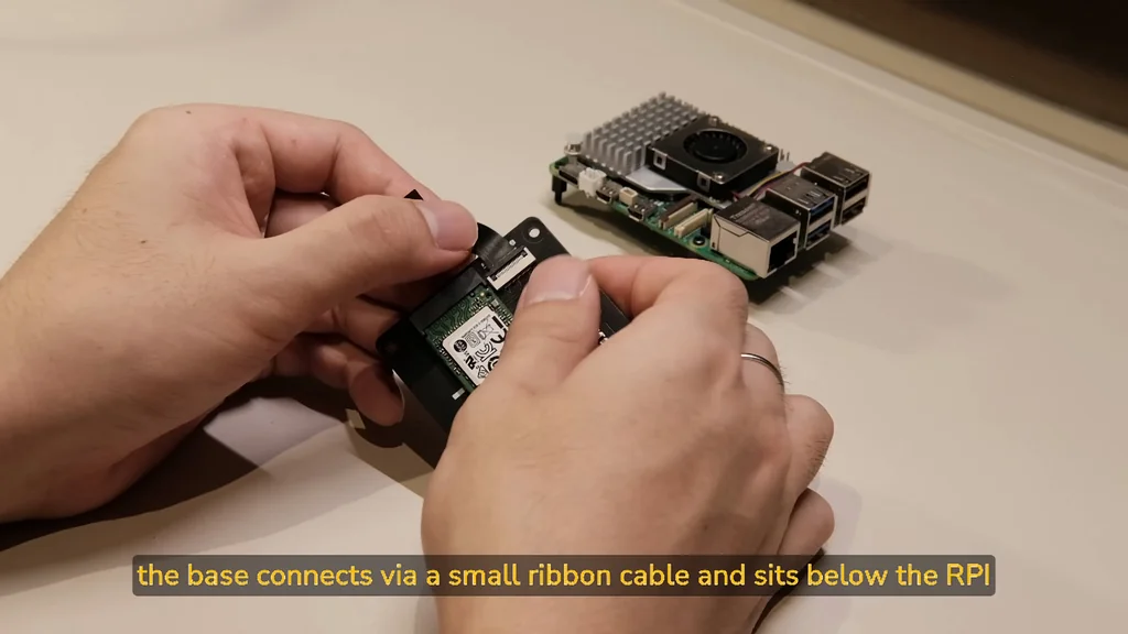
The top cover receives similar metal inserts to secure the rear backing panel. I'm installing the NVMe base using the spacers and screws included in the kit. The base connects to the Raspberry Pi via a small ribbon cable and sits directly beneath the board. It's a tight fit. Everything lines up perfectly. This configuration keeps the footprint small while providing high-speed storage for the system.
Mounting the Raspberry Pi and Display
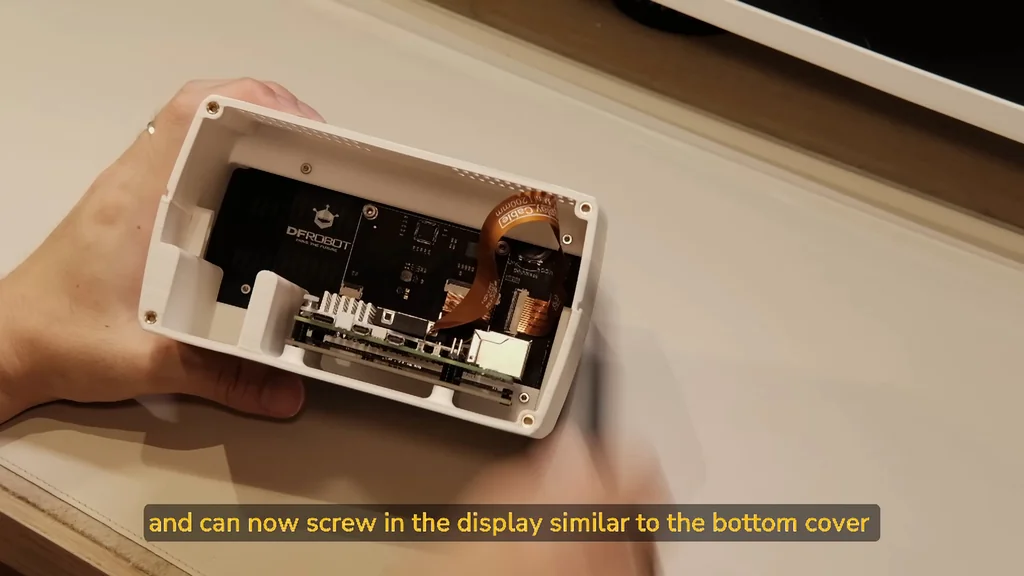
With the base prepared, I can now screw the Raspberry Pi and the NVMe adapter into the bottom cover. The alignment must be precise to ensure the ports clear the chassis openings. Next, the display installation begins. It connects to the Pi using a single ribbon cable. No external power supply is needed for the screen. It's clean and simple. The internal layout is efficient.
Assembling the Front Plate and Camera
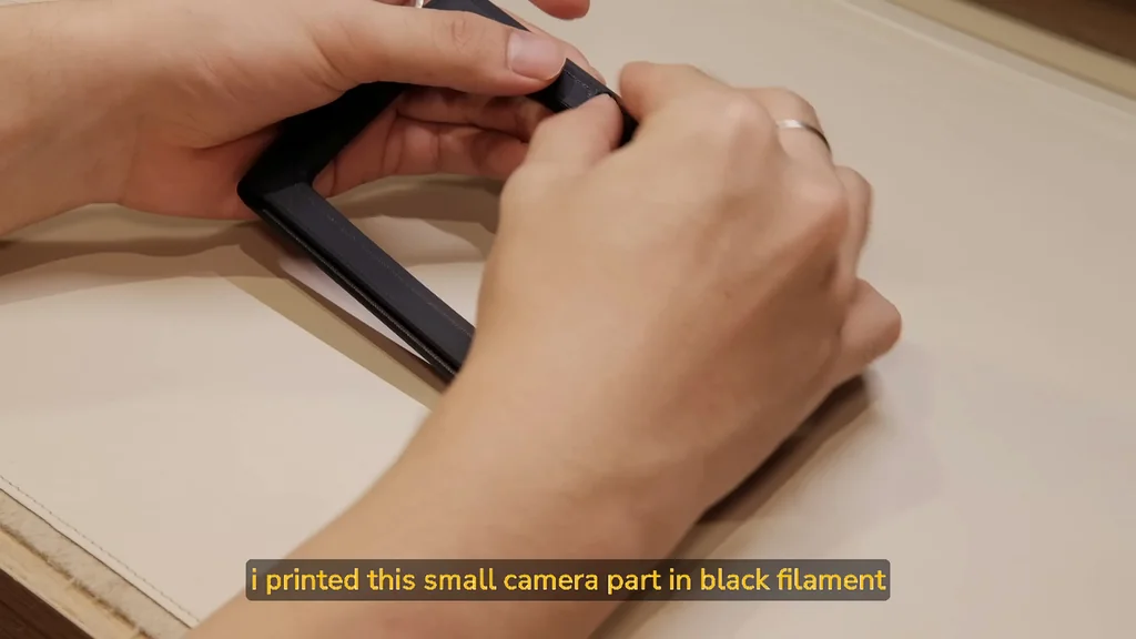
For the front plate, I'm using matte blue filament from eSUN to match the show's color palette. A small camera part, printed in black, screws directly into this front plate. It provides that authentic look. The fit is snug. It's a nice detail.
Locking the Chassis Components
The front knob is assembled and attached to the front plate. I slide the blue front plate into the bottom cover, then slide the top cover over to lock it into place. The screws for the display are already in the top cover, allowing me to secure the screen firmly. It's locked in. The structure feels rigid.
Integrating the Battery and Switch
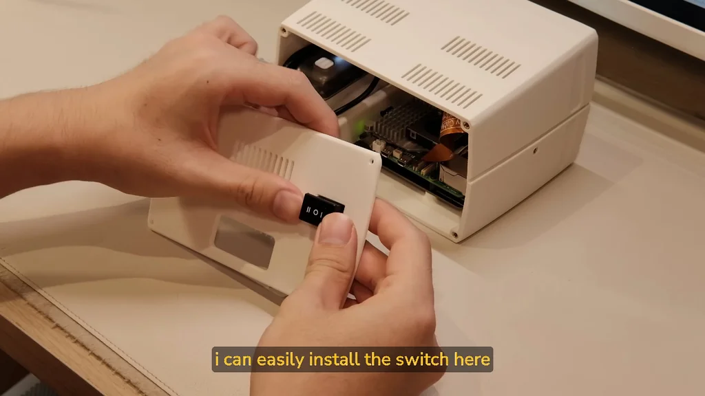
The battery pack is secured to the bottom with double-sided tape. Because it's a pass-through charger, the battery can be charged while simultaneously powering the Raspberry Pi. The backing panel is where the rocker switch is installed. It's an easy install. The wiring is tucked away.
Finalizing the Main Body
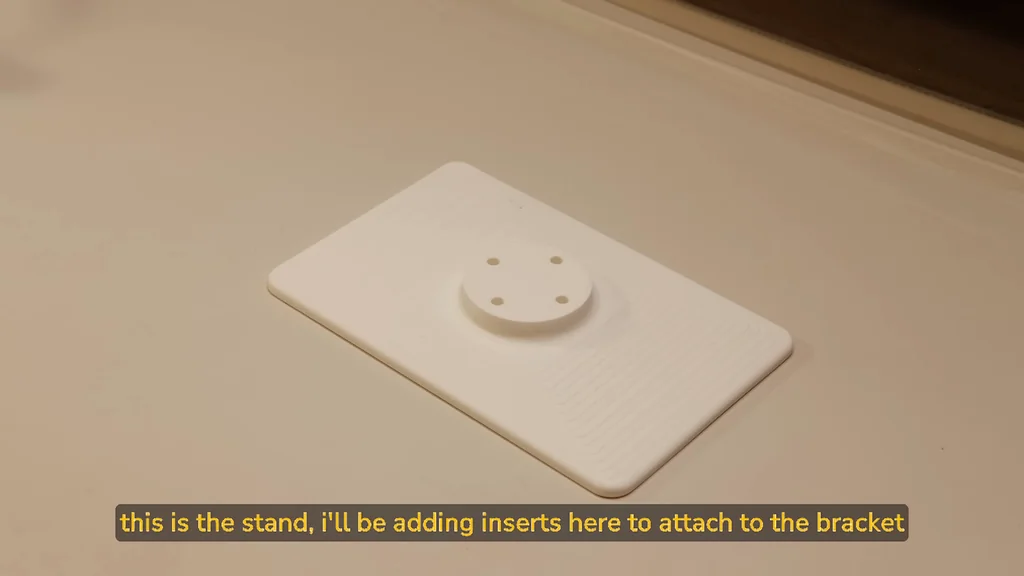
I noticed the USB-C cable was protruding slightly, so I updated the design to push the Pi further back for better cable clearance. The main body is now fully assembled. I'm adding inserts to the stand for the bracket attachment. It's ready now. The build is complete.
Constructing the Stand
The stand bracket attaches to the main stand using the metal inserts installed earlier. This provides a stable base for the computer. I'm also preparing the black ear knobs for the sides. It looks great. The stand is sturdy.
Attaching the Side Knobs
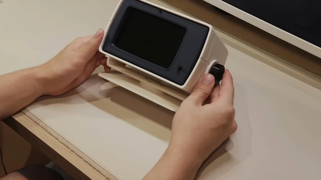
It's time to bring everything together. I screw the black ear knobs through the bracket and into the main body. This secures the unit to the stand. It's a simple process. The fit is perfect.
Final Assembly Check
The MDR computer is finished. Every component is seated and secured. It's ready for use. The build is complete.
Testing the Retro UI
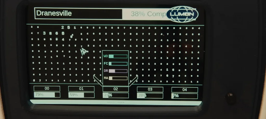
The final result is a functional, aesthetic piece of hardware. Running the retro UI on the screen completes the look. It works perfectly. Thanks for watching.
⚠️ CAUTION: SAFETY WARNING!
Ensure the battery pack is disconnected before performing any soldering or wiring work to prevent short circuits. Use caution when handling 3D printed parts near heat sources.
Summary & Tips
This project successfully bridges the gap between show-accurate design and functional computing. The use of threaded inserts ensures the assembly remains durable throughout its lifespan. It is a satisfying build for anyone looking to customize their Raspberry Pi setup. You now have a unique, portable workstation that pays homage to the MDR aesthetic.
📋 FAQ
❓ Can I use a different Raspberry Pi model?
Yeah, you could, but the case is specifically designed for the Pi 5's port layout. You might need to modify the CAD files if you use an older version.
❓ Is the battery pack included in the files?
Nah, the battery pack is a separate component you'll need to source. Check the bill of materials on the Patreon for the specific dimensions that fit the chassis.
❓ Do I need to use support material for printing?
Honestly, the design is optimized to be printed without supports. It saves a lot of time and makes the post-processing much easier.
❓ How hard is it to install the metal inserts?
Depends on your experience, but it's pretty straightforward. Just use your soldering iron to gently press them into the plastic holes while they are hot.
Disclaimer: I purchased all tools for this guide with my own money to ensure an unbiased review. This post contains affiliate links, meaning I earn a small commission if you make a purchase at no extra cost to you.