Nintendo updated the Switch 2 Joy-Con with magnetic rails, an optical mouse sensor, and larger thumbsticks, but the internal layout remains familiar. The design features standard tri-wing fasteners, sensitive rumble wiring, and resistive potentiometer tracks that still show vulnerability to stick drift.
⚡ Quick Guide: How to Make It in 12 Steps
- Remove outer tri-wing screws.
- Separate front housing and spine.
- Unplug battery and rumble motor.
- Extract shoulder trigger for concealed fasteners.
- Lift battery tray and ribbon cable.
- Detach mainboard and rail components.
- Unfasten shield for mouse sensor access.
- Pry analog module casing tabs.
- Check internal wiper contacts.
- Realign housing and secure tabs.
- Rebuild unit and verify click tension.
- Calibrate inputs on console.
📋 In This Article
- Technical Specifications & Components
- Tools & Materials Used — required items for this project
- Removing Outer Screws and Prying Front Housing
- Disconnecting Battery and Extracting Linear Rumble Motor
- Accessing Screws Trapped Under Shoulder Trigger
- Lifting Battery Frame and Trigger Flex Ribbon
- Removing Motherboard Screws and Rail Hardware
- Inspecting Optical Mouse Sensor and Magnetic Mounts
- Opening the Upgraded Analog Thumbstick Enclosure
- Analyzing Carbon Tracks and Drift Flaws
- Aligning Internal Wipers during Reassembly
- Fixing Broken R3 Tactile Click Mechanism
- Rebuilding Controller and Bench Testing Inputs
- Evaluating Serviceability and Modular Replacement
- FAQ
📊 Technical Specifications & Components
| Fasteners | Tri-wing Y00 & Phillips #00 screws |
| Internal Battery | Lithium-ion (~600 mAh) |
| Haptic Feedback | Linear resonant actuator |
| Secondary Sensor | Optical tracking assembly |
| Latch Mechanism | Magnetic lock plates |
| Analog Stick Type | Resistive wiper potentiometer |
| Stick Actuator | Tactile R3/L3 switch |
| Liquid Indicator | Paper contact strip |
📊 Project Overview & Costs
🔧 Difficulty Level: Medium
⏱️ Time Investment: DIY: 45 minutes | Pro: 20 minutes
💰 Professional Service Cost: $45 - $65
💡 Verdict: Repairing or cleaning the module prevents expensive unit replacement.
🛠️ Tools & Materials Used
• Plastic Pry Tool
• Fine Tip Tweezers
• Metal Spudger
Step-by-Step Guide
Removing Outer Screws and Prying Front Housing
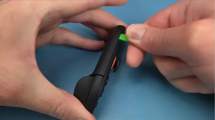
Start by using a tri-wing driver to remove the three outer housing fasteners. Two reside on the front edge with the third securing the top seam. Insert a plastic prying tool into the front seam rather than the back to avoid breaking the rear plastic clips. Once the perimeter is clear, the adhesive tape along the spine releases. Work slowly to prevent damaging the plastic edges.
Disconnecting Battery and Extracting Linear Rumble Motor
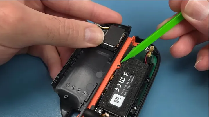
Tilt the back shell open, keeping the internal wiring clear. Using non-conductive tweezers, unplug the lithium battery to prevent shorts. The rumble motor lead is small, so tug gently on the wire housing to remove it. Slide the rear shell down to release the center latch clip. The linear motor is glued to the back cover, and the eject button pops out once the housing is clear.
Accessing Screws Trapped Under Shoulder Trigger
Four silver fasteners and one black corner screw sit inside the chassis. A fifth silver screw sits hidden under the trigger assembly. Do not force the frame. Instead, use a spudger to pop the four small peg clips holding the trigger button. With the button removed, there's a clear path to back out that final fastener.
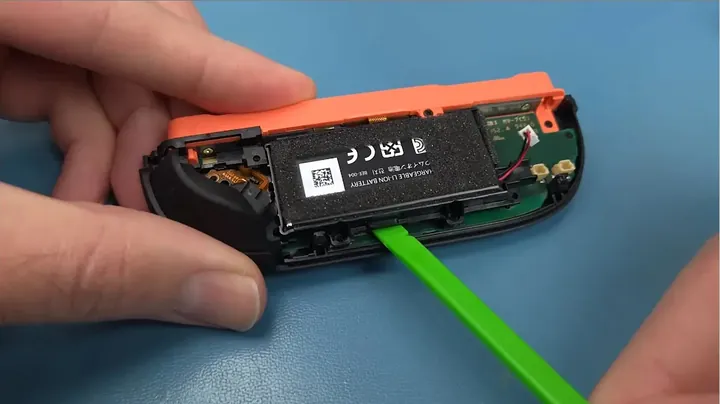
Lifting Battery Frame and Trigger Flex Ribbon
Once the five screws are out, lift the battery tray slowly. Pause to flip the ZIF connector latch for the shoulder button flex cable. Slide the ribbon out with tweezers. The battery isn't labeled, but it likely sits around 600 mAh. A water damage indicator sticker resides near the battery bay. Make sure not to strain the flex ribbon during this process.
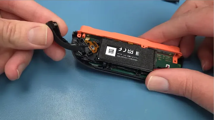
Removing Motherboard Screws and Rail Hardware
Detach the two remaining flex ribbons. Remove three black Phillips screws from the motherboard and two silver ones from the joystick. Lift the main board and detach the side rail. Four gold fasteners hold the internal metal shield in place. Pull that plate out to expose the final board screws. There are five total fasteners securing the main circuit board.
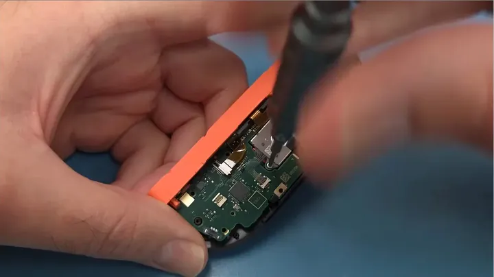
Inspecting Optical Mouse Sensor and Magnetic Mounts
Unclip the rail circuit to reach the optical sensor. The side housing contains large metal blocks that interface with the console's electromagnets. These contacts are modular, making them easy to swap if they wear out. The magnetic plates lock the unit securely. The optical sensor allows for flat surface tracking.
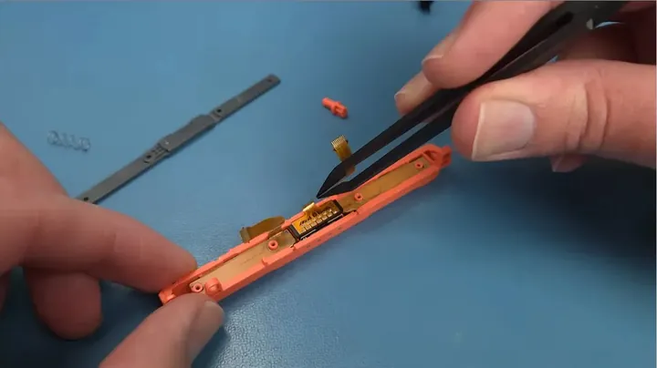
Opening the Upgraded Analog Thumbstick Enclosure
The Switch 2 stick is larger, but the internal construction is standard. A rubber collar sits on the neck. Four steel tabs lock the metal housing. Use a sharp spudger to pry up two of these tabs to split the shell. Tilt the cover back to avoid bending the metal too far. Careful prying is necessary here.

Analyzing Carbon Tracks and Drift Flaws
Inside, carbon tracks and metal wipers are coated in grease. This design still uses potentiometers rather than Hall-effect sensors. The friction causes material to flake off, eventually leading to drift. A plastic plunger handles the R3 click function. It's the same drift-prone design. Clean the carbon dust with isopropyl alcohol.
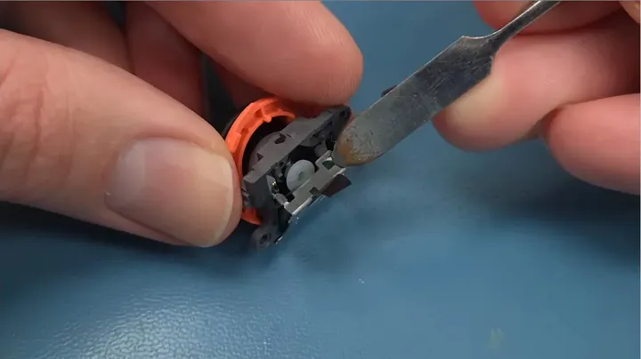
Aligning Internal Wipers during Reassembly
Carefully reseat the shaft spring and dual wipers. Align the actuator with the R3 button before closing the housing. Pressing the tabs back down is risky because the metal is thin. One tab can easily snap off. Fortunately, the outer plastic clips hold the assembly together effectively.
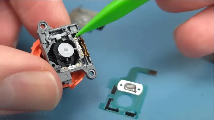
Fixing Broken R3 Tactile Click Mechanism
After reassembly, the R3 click felt mushy. The deformed metal cap was interfering with the switch plunger. Open the module again and adjust the tabs to release the pressure. Re-aligning the actuator fixes the click response. The tension is correct.
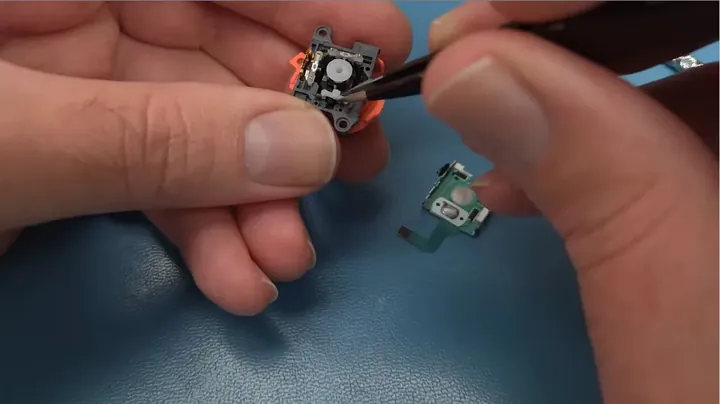
Rebuilding Controller and Bench Testing Inputs
Route the flex cables, lock the board, and reconnect the battery and motor. Tighten all screws, being careful not to strip the plastic. Once closed, run a calibration test in the system settings. It performs perfectly.
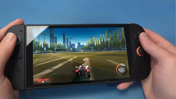
Evaluating Serviceability and Modular Replacement
The Switch 2 Joy-Con has improved modular rails, but the thumbsticks remain problematic. Repairing individual stick components is frustrating and risky. Swapping the entire stick module is the most efficient way to handle drift. Time will tell how these components hold up to regular use.
⚠️ CAUTION: SAFETY WARNING!
Unplug the battery before working on the board. Use plastic tools only to avoid puncturing the battery pouch.
Summary & Tips
The new Joy-Con features magnetic locks and better rail contacts. However, the stick drift issue persists due to the old potentiometer design. Replacing the entire stick module is recommended rather than opening the housing, as the metal tabs are prone to breaking.
📋 FAQ
❓ Does the Switch 2 Joy-Con use Hall effect joysticks?
No. It relies on traditional carbon track potentiometers. Drift is still possible over time, so module replacement is the preferred fix.
❓ What tools are needed to open a Switch 2 Joy-Con?
Required tools include a Y00 tri-wing driver, a PH00 Phillips bit, plastic pry tools, and tweezers. Stick to plastic tools for the shell.
❓ How are the Switch 2 Joy-Cons attached to the console?
They use magnetic plates and rails. The controller locks to electromagnets in the console, providing a firm, durable connection.
❓ Can I replace just the thumbstick module if it drifts?
Yes. The module is modular, making a full swap much easier than internal component repair.
❓ Where is the optical mouse sensor located on the controller?
It sits on the side rail under the internal shield, connecting to the board via a flex ribbon.
Disclaimer: All tools for this guide were purchased independently to ensure an unbiased review. This post includes affiliate links, which provide a small commission on sales.